E3 · HVAC Equipment and Components
Foundation lesson · 18 minute study sessionMatch the heat exchanger to its terminal temperatures.
Use flow arrangement, capacity rate and area basis to select a defensible heat-transfer method.
By the end of this lesson
- Pair the correct terminal temperature differences for counterflow.
- Apply the logarithmic mean and its equal-difference limit.
- Distinguish an LMTD calculation from effectiveness and NTU methods.
Two streams share one duty.
For a steady exchanger with negligible external loss, heat removed from the hot stream equals heat gained by the cold stream. Define capacity rate . Before sizing area, confirm that supplied flow rates and terminal temperatures can satisfy that balance.
Arrangement controls the driving differences.
Counterflow pairs hot inlet with cold outlet at one end, and hot outlet with cold inlet at the other. Parallel flow uses different pairs. The logarithmic mean captures the changing local temperature difference. A correction factor may be needed for a specified multipass or crossflow arrangement.
Unknown outlet temperatures call for another route.
When outlet temperatures are unknown, effectiveness and NTU can relate duty to capacity rates and . The maximum possible duty uses , not the sum of the two capacity rates. Overall U and area must refer to the same side and include the stated resistance or fouling basis.
A decision map for this lesson
Pair temperatures at the same physical end
For counterflow, the cold-fluid inlet is opposite the hot-fluid inlet. The existing terminal diagram uses the worked-example temperatures.
01 · Equipment view
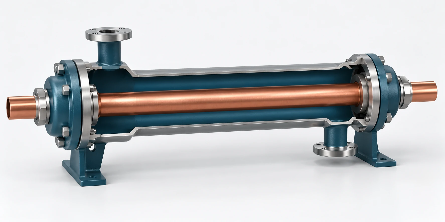
Hot stream · cold stream · two separated passages
Use the counterflow arrows in the schematic to pair temperatures at the same physical end.
02 · Exam-style model
Match temperatures at the same physical end: 180−110 on the left and 140−80 on the right. The flow arrows determine the pairing.
Original teaching figure. The schematic and stated givens define the model; the 3D view illustrates the hardware. These are not actual examination exhibits.
| Condition or question | Governing decision | Error to avoid |
|---|---|---|
| Both terminal temperatures are known | Pair the hot and cold temperatures at each physical end before finding LMTD. | Pairing both inlets merely because they are inlets. |
| Outlet temperatures are unknown | Use the appropriate effectiveness-NTU relation with the capacity rates and arrangement. | Inserting invented outlet temperatures into LMTD. |
| A supplied overall U is used | Match U and area to the same surface basis; include the stated correction factor. | Combining outside-area U with inside area without conversion. |
| Fouling resistance is specified | Add resistance on the consistent area basis and recalculate conductance. | Adding fouling resistance directly to U. |
On a narrow screen, scroll across the table to compare the decision and the error.
Relationships and their limits
Counterflow terminal differences
For the stated counterflow arrangement; both driving differences must be physically consistent.
LMTD area method
For equal terminal differences, use their common value. Apply the appropriate supplied correction factor F.
Effectiveness and NTU
The relation connecting effectiveness to NTU depends on arrangement and capacity-rate ratio.
| Symbol | Meaning | Units or basis |
|---|---|---|
| Overall coefficient on stated area basis | Btu/(h·ft²·°F) | |
| Heat-transfer area on matching basis | ft² | |
| Arrangement correction factor | dimensionless | |
| Stream heat-capacity rate | Btu/(h·°F) | |
| Heat exchanger effectiveness | dimensionless | |
| Logarithmic mean driving difference | °F difference | |
| Smaller stream heat-capacity rate | Btu/(h·°F) | |
| Number of transfer units | dimensionless | |
| Heat-transfer rate | Btu/h | |
| Hot-stream inlet and outlet temperatures | °F | |
| Cold-stream inlet and outlet temperatures | °F |
One decision, fully worked
Apply the method.
A counterflow exchanger has hot water entering at 180°F and leaving at 140°F; cold water enters at 80°F and leaves at 110°F. U = 100 Btu/(h·ft²·°F), area = 30 ft² on the matching basis and F = 1. Find the predicted duty for these terminal temperatures.
- Pair temperatures at the same physical ends of the counterflow exchanger.
- Compute the logarithmic mean of 70°F and 60°F.
- Multiply by the matching UA and the stated correction factor.
The predicted duty is about 194,600 Btu/h. To realize the specified temperatures, stream capacity rates must also support this duty.
Independent checkThe logarithmic mean lies between 60°F and 70°F. Required hot and cold capacity rates are about 4,865 and 6,487 Btu/(h·°F), giving the same duty over their 40°F and 30°F changes.
Specialist extension
State the overall-U area basis before adding fouling
An overall heat-transfer coefficient and its area must refer to the same surface. If all resistances and fouling factors are supplied on a common area basis, fouling adds resistance and reduces U. For a cylindrical wall or unequal areas, convert terms before adding them. For LMTD calculations, pair temperatures at the same physical exchanger end and apply the supplied arrangement correction factor.
A new applied case
Clean U is 100 Btu/(h·ft²·°F). A new fouling resistance is 0.002 h·ft²·°F/Btu on the same area basis.
Decision. Dirty U is about 83.333, on the supplied surface basis.
Cross-check. The added positive resistance must reduce U. It cannot increase heat transfer at otherwise fixed conditions.
Unit basis. U is Btu/(h·ft²·°F); fouling resistance is h·ft²·°F/Btu on the same area basis.
NCEES PE Mechanical Reference Handbook v2.1; see the module reference path.
Open targeted practice in the study studio →Transfer the method
Catch the common errors
- Pairing hot inlet with cold inlet for a counterflow terminal difference.
- Dividing by zero when both driving differences are equal instead of taking the limit.
- Using an inside-area U with an outside area.
Handbook navigation drill
Find it, then explain it.
Search: Log Mean Temperature Difference; effectiveness
Find the LMTD and effectiveness sections. Sketch the two counterflow ends before writing the temperature differences.
Check your navigation
Section 5.5 supplies exchanger relationships. The correction factor and effectiveness relation depend on arrangement; they are not interchangeable constants.
Reference path: §5.5, pp. 312–314. These are printed handbook page numbers; section names and search terms remain the primary navigation method. See technical review status.
Deeper application · Decision Lab
Unknown outlet temperatures: choose the exchanger model
Choose a method before assuming an outlet temperature. Then test whether changing the flow arrangement preserves the result.
Choose the method, predict the changed-condition result and inspect the complete cross-check. Sign in before starting to keep your first response and later reflection in the separate reasoning notebook.
Open the original workshop →Theory sources
- NCEES PE Mechanical Reference Handbook v2.1: §5.5, pp. 312–314
- Mechanical and Electrical Equipment for Buildings, 12th ed.: mechanical systems and energy principles. Supporting theory; not an examination reference.
Worked examples and lesson prose are original ReasonSpan™ material. Obtain authorized publications separately; this preview does not reproduce the supplied books or handbook.