D3 · HVAC and Refrigeration Distribution and Systems
Foundation lesson · 25 minute study sessionBalance water duty and pump head separately
Thermal capacity sets hydronic flow; the pressure-loss network sets pump head. Elevation means different things in open and closed systems.
By the end of this lesson
- Calculate water flow from thermal duty.
- Identify series losses and the controlling parallel route.
- Explain why closed-loop elevation does not equal pump lift.
Thermal duty sets flow
For ordinary liquid water near conventional HVAC temperatures, the familiar coefficient of about 500 connects Btu/h, gpm and °F. It assumes a suitable water density and heat capacity. Glycol, unusual temperatures or supplied properties require the general mass-flow relationship. The thermal relation uses ; pump head follows the hydraulic boundary.
The network sets head
Pipe friction and component losses consume pump head. Parallel branches share the pressure difference between their junctions; flows add. The controlling route and balancing requirements set the design operating point. The pump operating point lies where the pump curve meets the system curve.
Distinguish open from closed
In a filled closed loop, upward and downward static elevation changes balance around the circuit. The pump must overcome flow losses, not continuously lift all water through the full building height. Static fill pressure is still needed to maintain acceptable pressure at high points and avoid vapor formation. In an open system, a net elevation difference may contribute directly to required pump head.
A decision map for this lesson
Separate thermal flow from circulation head
The closed-loop illustration uses the worked example: flow comes from heat duty, while head comes from the controlling hydraulic route.
01 · Equipment view
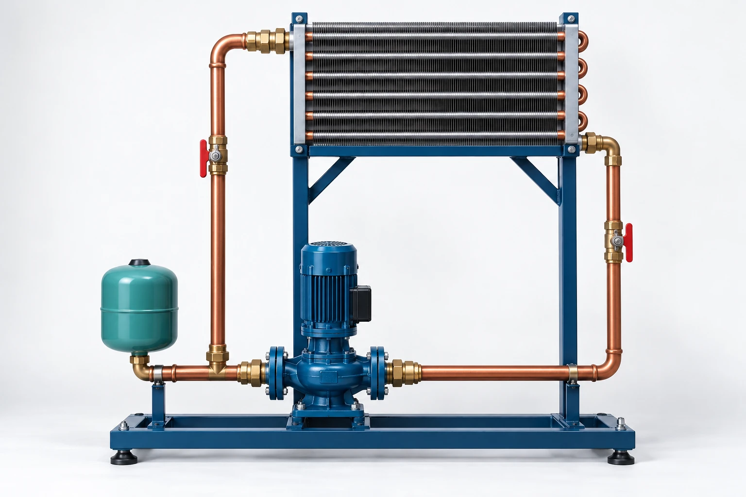
Pump → supply riser → elevated coil → return
The schematic traces one filled closed loop. Equipment elevation affects fill pressure; circulation head follows the complete loop losses.
02 · Exam-style model
The 40-ft rise has a matching return drop. It affects local pressure and fill requirements, but is not added to this closed-loop circulation head.
Original teaching figure. The schematic and stated givens define the model; the 3D view illustrates the hardware. These are not actual examination exhibits.
| Condition or question | Governing decision | Error to avoid |
|---|---|---|
| Required water flow | Use only for the stated ordinary-water approximation. | Carrying the same factor into a different fluid-property basis without checking it. |
| A filled, closed circulation loop | Sum friction and component losses; the net hydrostatic rise cancels around the loop. | Adding the building height to circulation head. |
| An open system or imposed pressure difference | Include the net elevation and pressure terms as well as losses. | Applying the closed-loop cancellation to unequal free surfaces. |
| Pump suction performance | Use absolute pressure head, liquid level, vapor pressure and suction loss for NPSH. | Treating circulation head or fill pressure as a complete NPSH check. |
On a narrow screen, scroll across the table to compare the decision and the error.
Relationships and their limits
General thermal balance
Use actual fluid density and heat capacity when provided.
Water approximation
Btu/h, gpm, °F; appropriate ordinary-water approximation only.
| Symbol | Meaning | Units or basis |
|---|---|---|
| Thermal duty | Btu/h | |
| Fluid mass flow | lb/h | |
| Fluid specific heat | Btu/(lb·°F) | |
| Liquid volumetric flow | gpm | |
| Required pump head | ft of stated liquid | |
| Fluid temperature change | °F difference |
One decision, fully worked
Apply the method.
A closed chilled-water loop serves a 150,000 Btu/h coil at a 12°F water-temperature rise. Use the ordinary-water factor 500. At this flow, the controlling route has 18 ft of pipe/fitting loss and 12 ft of coil/valve loss. The building elevation difference is 40 ft; the loop is filled and closed.
- Calculate water flow from the coil heat balance.
- Add losses on the controlling route.
- Do not add the closed-loop elevation difference to operating head.
The stated operating requirement is 25 gpm at 30 ft of head, before any additional explicitly required allowances.
Independent checkAdding 40 ft of closed-loop elevation would mix fill-pressure requirements with circulating head.
Specialist extension
Check NPSH margin at the selected operating flow
For an open reservoir, available NPSH is absolute surface-pressure head plus signed surface elevation above the pump datum, minus vapor-pressure head and suction losses. Use all terms as head of the pumped liquid. Required NPSH is the manufacturer’s characteristic at the selected flow and speed. Rising temperature increases vapor pressure and can reduce availability. A positive difference from NPSHR does not automatically satisfy every manufacturer’s recommended margin.
A new applied case
At the selected flow, absolute surface-pressure head is 33.9 ft of the liquid, its surface is 4.0 ft above the pump datum, vapor-pressure head is 5.0 ft and suction loss is 3.0 ft. Supplied NPSHR is 8.0 ft and the required additional margin is 3.0 ft.
Decision. The stated 3.0 ft additional-margin criterion is satisfied.
Cross-check. For suction lift, the surface-elevation term is negative. Do not substitute gauge surface pressure for the supplied absolute head.
Unit basis. All pressure, elevation and loss terms are ft of the pumped liquid; NPSHR is at the selected flow and speed.
ASHRAE Pocket Guide for Air Conditioning, Heating, Ventilation, Refrigeration, SI, 9th ed. (2017), printed pp. 70–71, supporting fundamentals. This original USCS example converts the pressure basis to head explicitly; the guide is not an examination reference.
Open targeted practice in the study studio →Transfer the method
Catch the common errors
- Adding closed-loop building height to circulating pump head.
- Summing unrelated parallel branch losses.
- Using the water coefficient for glycol without checking properties.
Handbook navigation drill
Find it, then explain it.
Search: Centrifugal Pump Characteristics
Locate pump and system-curve concepts and the pump power equation.
Check your navigation
You can explain the distinction between static pressure, head loss and the operating point.
Reference path: §3.3; §3.7.4–3.7.6, pp. 255–259; §9.6, pp. 533–535. These are printed handbook page numbers; section names and search terms remain the primary navigation method. See technical review status.
Theory sources
- NCEES handbook v2.1, §§3.3, 3.7.4–3.7.6 and 9.6.
- Grondzik and Kwok, Mechanical and Electrical Equipment for Buildings, 12th ed., §§12.10 and 12.12.
Worked examples and lesson prose are original ReasonSpan™ material. Obtain authorized publications separately; this preview does not reproduce the supplied books or handbook.