L1 · HVAC Loads and Psychrometrics
Foundation lesson · 25 minute study sessionBuild the thermal path before calculating a load
A correct load begins with a physical boundary and the right thermal path. More insulation, shading and thermal mass affect a building in different ways.
By the end of this lesson
- Distinguish heat gain from cooling load.
- Combine series resistances and parallel heat-flow paths.
- Use the correct area and design temperature difference.
Choose the boundary
Heat gain is energy entering the space. Cooling load is the rate that must be removed to hold the desired conditions at a particular time. Radiation absorbed by room surfaces may become a cooling load later. Equipment load can also include outdoor-air treatment, duct gains and fan heat. Identify which quantity the problem requests before adding terms. Define on the full assembly area and verify that .
Series and parallel paths
For a uniform layer, area-normalized thermal resistance is thickness divided by conductivity. Add layers in series, including surface films when applicable. Framing and insulation paths act in parallel: calculate each path U-factor and area-weight those U-factors. Averaging their R-values gives the wrong assembly performance.
Solar gain and storage
Opaque conduction, glazing conduction and solar gain are separate contributions. If a problem supplies incident solar irradiance and SHGC, multiply them by the applicable glazing area. Thermal mass shifts heat flow in time; it does not substitute for insulation. Passive strategies help explain load reduction, but the examination calculation must follow the stated design method and data.
A decision map for this lesson
Choose the thermal path before the coefficient
Separate series layers from parallel area paths before calculating the assembly heat rate.
01 · Equipment view
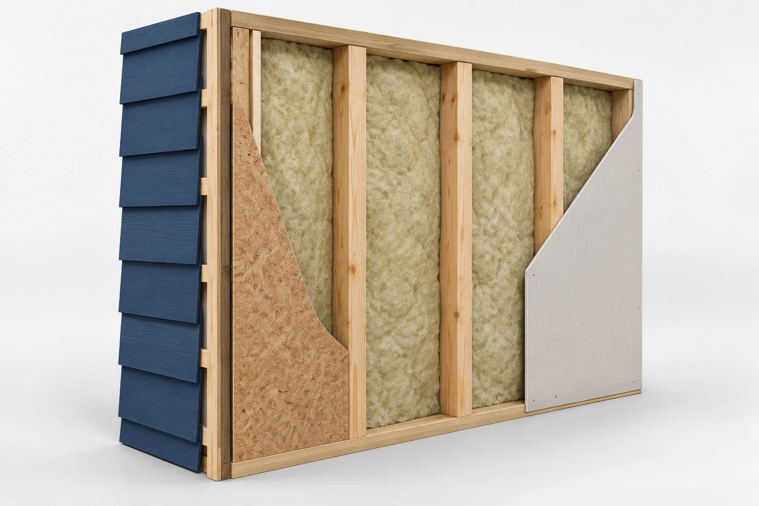
Insulated bay · framing path · common wall faces
Read the area fractions and complete path resistances in the model; the cutaway is not an area-scale drawing.
02 · Exam-style model
Use parallel path conductances, then apply the common area and temperature difference. The stated path resistances include films.
Original teaching figure. The schematic and stated givens define the model; the 3D view illustrates the hardware. These are not actual examination exhibits.
| Condition or question | Governing decision | Error to avoid |
|---|---|---|
| Layers along one heat path | Add area-normalized resistances: . Then . | Adding conductances for layers that are in series. |
| Framing and insulated bays side by side | Weight path conductances by area: . | Averaging the path R-values instead of their conductances. |
| A supplied U or R already includes films | Use the stated assembly basis and count each physical resistance once. | Adding inside and outside films again. |
| An instantaneous space peak | Check timing, thermal storage and simultaneous zone loads. | Treating steady conduction or separate zone maxima as the complete coincident peak. |
On a narrow screen, scroll across the table to compare the decision and the error.
Relationships and their limits
Area-normalized resistance
Keep thickness and conductivity units consistent. U includes all resistances included in the specified assembly.
Parallel paths
Area fractions sum to one. This is a steady-state conduction relationship, not a complete transient cooling-load method.
| Symbol | Meaning | Units or basis |
|---|---|---|
| Area-normalized thermal resistance | h·ft²·°F/Btu | |
| Overall heat-transfer coefficient | Btu/(h·ft²·°F) | |
| Area fraction for path i | dimensionless | |
| Assembly area | ft² | |
| Heat-transfer rate | Btu/h | |
| Driving temperature difference | °F difference | |
| Layer thickness | ft | |
| Layer conductivity | Btu/(h·ft·°F) |
One decision, fully worked
Apply the method.
An opaque wall has 800 ft² of net area. Insulated bays occupy 85% with R-20; framing occupies 15% with R-6. The stated path R-values already include films. The design temperature difference is 35°F. Find steady-state heat transfer.
- Use the net opaque wall area; no window area is included.
- Invert each path resistance before weighting.
- Combine U-factors using the stated fractions.
- Multiply assembly U by area and temperature difference.
The wall transfers 1,890 Btu/h under the stated steady-state conditions.
Independent checkThe assembly R-value is about 14.8, lower than R-20 because framing bypasses some insulation.
Specialist extension
Turn an envelope limit into a design requirement
A design constraint is often given as an allowable heat rate rather than a required R-value. Solve for total resistance on the stated area basis, then subtract the layers already present. For parallel paths, solve the conductance-weighted area fractions instead. A steady conduction target does not by itself establish the hourly cooling peak of a massive enclosure.
A new applied case
An 800 ft² roof has existing series resistance 6 h·ft²·°F/Btu. At a 45°F difference, conductive gain must not exceed 1,800 Btu/h. Ignore thermal bridges.
Decision. Add at least 14 on this resistance and area basis.
Cross-check. Substitution gives 800 × 45 / (6 + 14) = 1,800 Btu/h.
Unit basis. A is area in ft²; ΔT is °F; heat rate is Btu/h; area-normalized R is h·ft²·°F/Btu.
NCEES PE Mechanical Reference Handbook v2.1; see the module reference path.
Open targeted practice in the study studio →Transfer the method
Catch the common errors
- Averaging R-values across parallel paths.
- Adding film resistance again when already included.
- Calling instantaneous heat gain a complete equipment cooling load.
Handbook navigation drill
Find it, then explain it.
Search: Thermal Resistance
Find the composite-wall relationship and identify whether the resistance is for the whole object or per unit area.
Check your navigation
Your units reduce to Btu/h after multiplying U, area and temperature difference.
Reference path: §5.1–5.2, pp. 303–308; §9.1, pp. 446–478. These are printed handbook page numbers; section names and search terms remain the primary navigation method. See technical review status.
Theory sources
- NCEES PE Mechanical Reference Handbook v2.1, §§5.1–5.2 and 9.1.9–9.1.13.
- Grondzik and Kwok, Mechanical and Electrical Equipment for Buildings, 12th ed., ch. 7, Heat Flow.
- Lechner, Heating, Cooling, Lighting, 4th ed., chs. 3 and 9.
- Brown and DeKay, Sun, Wind & Light, 3rd ed., Energy Programming and climate-responsive load reduction.
Worked examples and lesson prose are original ReasonSpan™ material. Obtain authorized publications separately; this preview does not reproduce the supplied books or handbook.