D7 · HVAC and Refrigeration Distribution and Systems
Foundation lesson · 30 minute study sessionBalance the refrigeration cycle and the stored product
A refrigeration system moves heat and adds compressor work. Evaporator duty, condenser rejection and product freezing load are different quantities.
By the end of this lesson
- Name the four vapor-compression processes.
- Calculate COP and condenser heat rejection.
- Split a freezing load into sensible and latent intervals.
Follow the four states
For a basic vapor-compression cycle, the compressor raises pressure and enthalpy; the condenser rejects heat; the throttling device reduces pressure approximately at constant enthalpy; the evaporator absorbs the refrigeration duty. State enthalpies must refer to the same refrigerant and datum. Preserve the labeled states when forming and .
Use the right performance ratio
Refrigeration COP is evaporator heat absorbed divided by compressor work. Heat-pump heating COP uses condenser heat delivered. Express numerator and denominator in consistent energy units. The condenser rejects evaporator duty plus compressor work for the stated idealized boundary.
Include storage and product loads
Cold-storage loads may include envelope heat gain, infiltration, lights, people, fans, product cooling and respiration. A product taken through freezing needs separate sensible cooling above freezing, latent freezing and sensible cooling below freezing. Supplied food properties control the result. Refrigerant safety classifications and handling concepts belong in the supportive-knowledge review.
A decision map for this lesson
Follow the cycle states and the product boundary
Read each enthalpy at its physical location; product pull-down is a separate load calculation.
01 · Equipment view
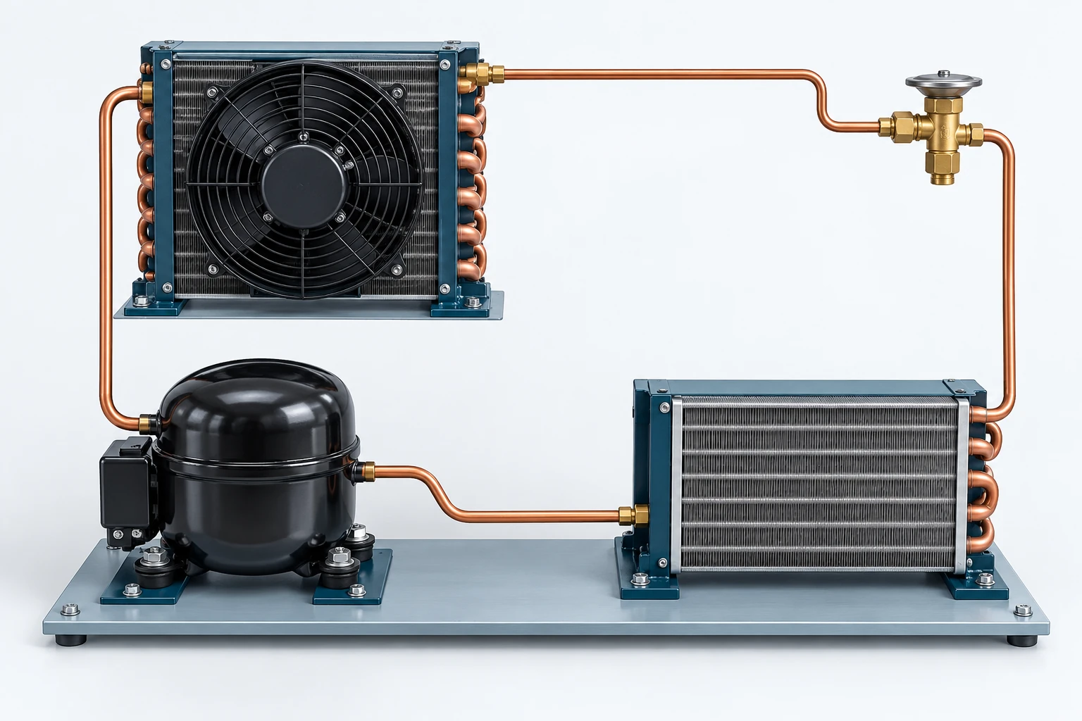
Compressor → condenser → expansion valve → evaporator
Use the numbered state points and flow direction in the schematic. Pipe lengths and equipment sizes are illustrative.
02 · Exam-style model
Locate the physical state before selecting its enthalpy. Under the stated basic throttling model, h₄ equals h₃.
Original teaching figure. The schematic and stated givens define the model; the 3D view illustrates the hardware. These are not actual examination exhibits.
| Condition or question | Governing decision | Error to avoid |
|---|---|---|
| Evaporator duty | Use . | Using condenser enthalpy drop as the useful refrigeration effect. |
| Compressor work | Use for the stated steady enthalpy-rise model. | Taking compressor electrical input as refrigerant work when other losses are included. |
| Basic adiabatic throttling | Use when kinetic/potential changes and external heat are neglected. | Assuming the throttle preserves temperature instead of enthalpy. |
| Product cooling and freezing | Sum pre-freeze sensible energy, latent freezing energy and post-freeze sensible energy; divide by the stated time. | Counting product energy as an hourly rate without the processing-time conversion. |
On a narrow screen, scroll across the table to compare the decision and the error.
Relationships and their limits
Cycle duties
Basic steady cycle; throttling is approximated by = ; kinetic/potential changes neglected.
COP and heat rejection
Energy rates must use the same units. Heating COP uses in the numerator.
Product through freezing
Use supplied freezing temperature, latent heat and specific heats; this is total energy, not a rate.
| Symbol | Meaning | Units or basis |
|---|---|---|
| Specific enthalpy at labeled cycle state | Btu/lb refrigerant | |
| Evaporator heat per unit refrigerant mass | Btu/lb | |
| Compressor work per unit mass | Btu/lb | |
| Condenser heat rejection | Btu/h | |
| Refrigeration coefficient of performance | dimensionless | |
| Condenser heat per unit refrigerant mass | Btu/lb | |
| Compressor input rate | Btu/h on matching basis | |
| Total product cooling/freezing energy | Btu | |
| Product mass | lb | |
| Product heat capacity above/below freezing | Btu/(lb·°F) | |
| Supplied latent freezing energy | Btu/lb | |
| Initial, freezing and final product temperatures | °F |
One decision, fully worked
Apply the method.
A refrigeration cycle has h₁ = 100, h₂ = 125, h₃ = 40 and h₄ = 40 Btu/lb. Refrigerant flow is 2,000 lb/h. Ignore heat losses and kinetic/potential changes. Find evaporator duty, compressor energy input and condenser rejection.
- Use h₁ − h₄ for refrigerating effect.
- Use h₂ − h₁ for compressor work.
- Multiply each specific quantity by refrigerant mass flow.
- Check condenser rejection against evaporator duty plus input.
The evaporator provides 120,000 Btu/h with COP 2.4; condenser rejection is 170,000 Btu/h.
Independent check120,000 + 50,000 equals 170,000 Btu/h. The condenser rejects more heat than the evaporator absorbs.
Specialist extension
Divide a freezing duty into physical stages
Product refrigeration can include cooling above freezing, latent freezing, and cooling below freezing. Use the appropriate supplied heat capacity for each temperature interval and apply the latent term only to the mass or fraction that freezes. Divide total energy by the allowed processing duration and add other stated coincident room duties on the same rate basis.
A new applied case
A 1,000 lb product is cooled from 40°F to 30°F with cp = 0.8 Btu/(lb·°F), completely frozen at 30°F using 100 Btu/lb, then cooled to 0°F with cp = 0.4. Processing takes 4 h. Other loads are zero.
Decision. Average product duty is 2.5 refrigeration tons.
Cross-check. The sensible contributions are 8,000 and 12,000 Btu; the latent contribution is 100,000 Btu. None should be counted twice.
Unit basis. Product mass is lb; cp is Btu/(lb·°F); latent freezing energy is Btu/lb; refrigeration ton is 12,000 Btu/h.
NCEES PE Mechanical Reference Handbook v2.1; see the module reference path.
Open targeted practice in the study studio →Transfer the method
Catch the common errors
- Using condenser heat to calculate refrigeration COP.
- Treating the expansion valve as isentropic instead of approximately isenthalpic.
- Dividing total product energy by time before all cooling/freezing terms are included.
Handbook navigation drill
Find it, then explain it.
Search: Compression Refrigeration Cycles
Follow the refrigeration cross-reference to thermodynamic cycles, then locate refrigerant and food property tables.
Check your navigation
You can identify which property table and cycle state are needed before calculating.
Reference path: §4.5, pp. 289–302; §8.1–8.10, pp. 401–445. These are printed handbook page numbers; section names and search terms remain the primary navigation method. See technical review status.
Theory sources
- NCEES handbook v2.1, §4.5 and §§8.1–8.10.
- Grondzik and Kwok, Mechanical and Electrical Equipment for Buildings, 12th ed., §§12.7–12.8.
- Lechner, Heating, Cooling, Lighting, 4th ed., §§16.9–16.10.
Worked examples and lesson prose are original ReasonSpan™ material. Obtain authorized publications separately; this preview does not reproduce the supplied books or handbook.