S4 · Supportive Knowledge (HVAC and Refrigeration)
Foundation lesson · 25 minute study sessionKeep electrical input, shaft output and room heat separate
Motor power factor and efficiency describe different conversions. A nameplate shaft rating is not the real electrical input, and the room heat depends on where the work goes.
By the end of this lesson
- Calculate three-phase real input from voltage, current and power factor.
- Convert shaft output through motor efficiency.
- Locate motor losses and driven-load dissipation.
Real and apparent power
For a balanced three-phase load, apparent power uses line voltage and line current. Real power additionally includes power factor. Motor efficiency relates shaft output to real electrical input. Power factor does not replace efficiency, and efficiency does not replace power factor. . The room boundary determines which term becomes room heat.
Define where energy becomes heat
Motor losses are input minus shaft output. If the motor and driven equipment are inside the conditioned boundary and all work ultimately dissipates there, the total electrical input can become room heat. If the motor is inside but shaft work leaves the boundary, room heat may be only the motor losses. State the physical boundary before applying a heat factor.
Read ratings carefully
A horsepower rating generally describes mechanical output under the stated operating condition. Do not assume rated output, full-load current, operating efficiency or continuous duty when the question supplies a different condition. Use the problem data rather than inferring a manufacturer performance curve.
A decision map for this lesson
Track real input, shaft work and room heat
Power factor connects real and apparent input. Motor efficiency connects real input and shaft output. The room boundary determines heat gain.
01 · Equipment view
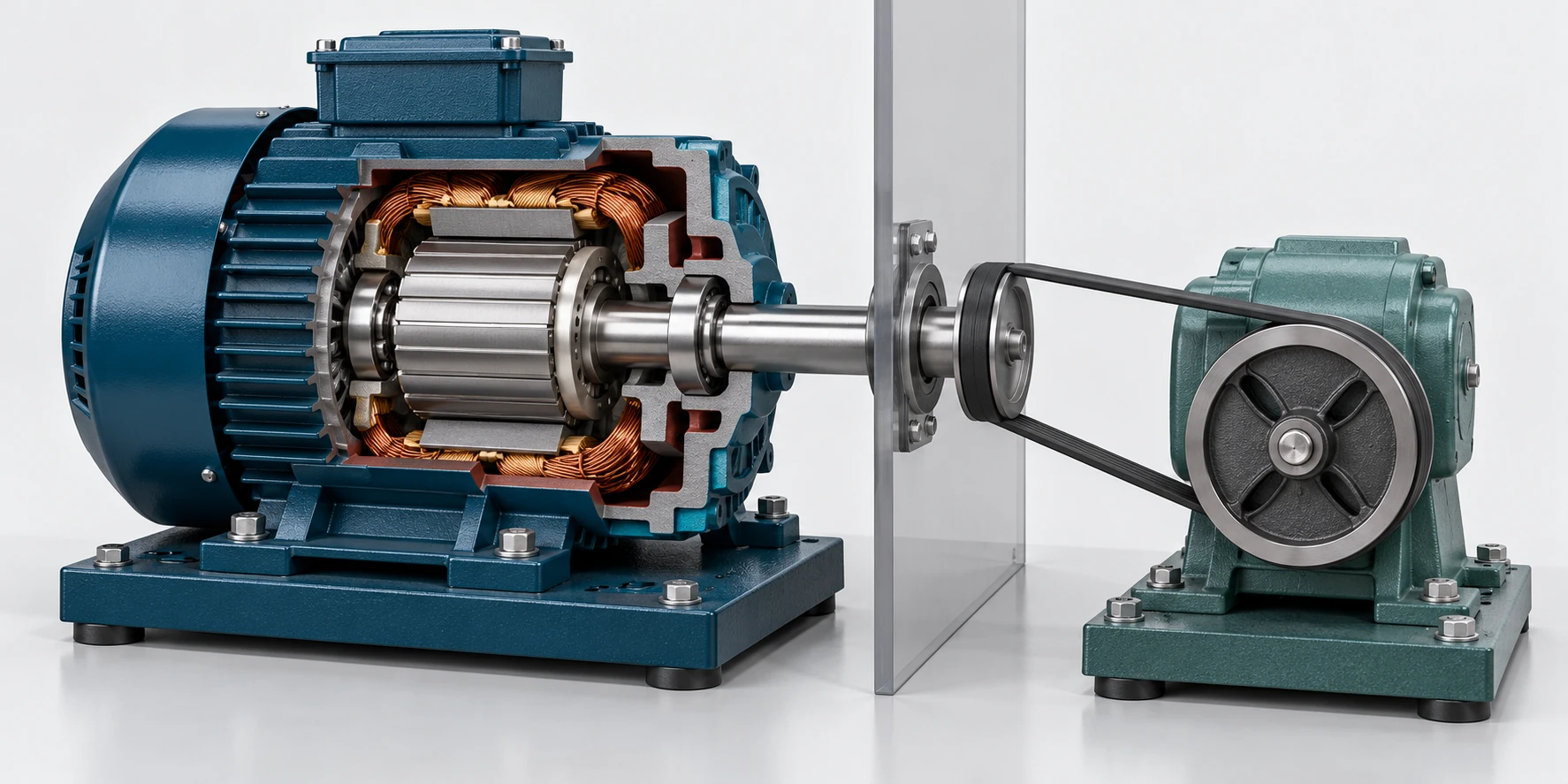
Motor inside room → shaft work exported
The partition illustrates the room boundary. Only the stated motor losses remain inside for this case; shaft work leaves and does not return as room heat.
02 · Exam-style model
For this worked example, shaft work leaves the room and does not return as heat. A larger boundary containing the driven dissipation would give a different room gain.
Original teaching figure. The schematic and stated givens define the model; the 3D view illustrates the hardware. These are not actual examination exhibits.
| Condition or question | Governing decision | Error to avoid |
|---|---|---|
| Electrical supply loading is requested | Use the stated phase relation and power factor; . | Using shaft power as apparent electrical input. |
| Motor input or shaft output is requested | Use on one consistent power basis. | Applying power factor again to an input already stated as real kW. |
| Motor is inside; shaft work is exported | Count retained motor losses as room heat under the stated boundary. | Including exported shaft work in the room heat gain. |
| Motor and driven work both dissipate inside | Under steady conditions with no export, all real input eventually becomes room heat. | Counting motor losses alone for the larger complete room boundary. |
On a narrow screen, scroll across the table to compare the decision and the error.
Relationships and their limits
Balanced three-phase power
P in kW, line voltage in V and line current in A. Applies to the stated balanced three-phase load.
Motor efficiency
Use real electrical input for efficiency; output and input must be in the same units.
Power to heat
This is an energy-rate conversion; only energy entering the chosen thermal boundary belongs in its heat load.
| Symbol | Meaning | Units or basis |
|---|---|---|
| Real electrical input | kW | |
| Mechanical shaft output | kW | |
| Motor dissipation | kW | |
| Line voltage | V | |
| Line current | A | |
| Power factor | dimensionless | |
| Motor efficiency | dimensionless |
One decision, fully worked
Apply the method.
A motor produces 10 hp at 90% efficiency. Use 1 hp = 0.746 kW and 1 kW = 3,412 Btu/h. The motor is inside a conditioned room but its shaft work leaves the room and does not return as heat. Find electrical input and motor heat added to the room.
- Convert shaft output to kW.
- Divide shaft output by efficiency to find real input.
- Subtract shaft output to find motor losses.
- Convert only the losses to room heat for the stated boundary.
Real electrical input is about 8.29 kW; room heat from the motor is about 2,830 Btu/h.
Independent checkIf all shaft work were dissipated inside the room, the room heat would instead approach the full electrical input, about 28,280 Btu/h.
Specialist extension
Keep real power, apparent power and shaft output separate
For a balanced three-phase load, use line voltage and line current with the square-root-of-three factor. Power factor connects real and apparent input, while motor efficiency connects real input to shaft output. Use real input for energy and heat balances; apparent power also affects supply loading. Do not apply power factor a second time to a value already stated as real kW.
A new applied case
A balanced motor has 400 V line voltage, 18 A line current and PF = 0.80. Motor efficiency is 0.90.
Decision. Real input is about 9.977 kW and shaft output about 8.979 kW.
Cross-check. Apparent input is about 12.471 kVA; power factor is distinct from the 90% conversion efficiency.
Unit basis. VL is line volts; IL is line amperes; PF and efficiency are dimensionless; real/shaft power is kW.
NCEES PE Mechanical Reference Handbook v2.1; see the module reference path.
Open targeted practice in the study studio →Transfer the method
Catch the common errors
- Multiplying output by efficiency to obtain input.
- Using apparent kVA as real kW.
- Counting shaft work as room heat after the stem explicitly sends it outside the boundary.
Handbook navigation drill
Find it, then explain it.
Search: Electrical Concepts of Motors
Locate efficiency, power factor and full-load-current relationships, then compare the motor heat-gain table.
Check your navigation
You can select the motor heat case from the equipment location and work boundary.
Reference path: §1.11, pp. 85–88; §9.1.4, p. 448. These are printed handbook page numbers; section names and search terms remain the primary navigation method. See technical review status.
Theory sources
- NCEES handbook v2.1, §§1.11 and 9.1.4.
- Grondzik and Kwok, Mechanical and Electrical Equipment for Buildings, 12th ed., ch. 12, motor heat and active climate-control principles.
Worked examples and lesson prose are original ReasonSpan™ material. Obtain authorized publications separately; this preview does not reproduce the supplied books or handbook.