D1 · HVAC and Refrigeration Distribution and Systems
Foundation lesson · 25 minute study sessionFollow the controlling air path
Duct branches do not all carry the same air or require their losses to be added together. Trace the actual route and define the pressure quantity before selecting a fan.
By the end of this lesson
- Use continuity to size a duct cross section.
- Distinguish parallel branches from one pressure-loss route.
- Separate static, velocity and total pressure.
Continuity comes first
Duct volume flow equals cross-sectional area times mean velocity. Use consistent length units. A rectangular duct dimension in inches must be converted before area is compared with a velocity in ft/min. Flows add where branches merge; the same steady flow passes along a series segment without leakage. Convert dimensions before forming , then use .
Build a pressure budget
A route contains duct friction, fittings, dampers, terminals and other components. For parallel branches, calculate each complete route and use the controlling requirement; summing all parallel branch losses does not represent a real air path. Balance lower-resistance branches as required by the system design.
Match the fan pressure basis
Total pressure is static pressure plus velocity pressure. Fan static and fan total pressure are distinct rating quantities. Fan selection must use the pressure definition and test configuration supplied by the question. A higher-efficiency filter can change pressure loss, shifting the operating point.
A decision map for this lesson
Read the route, then size the section
A shared loss belongs to every route. Parallel branch losses are compared, rather than added as one series path.
01 · Equipment view
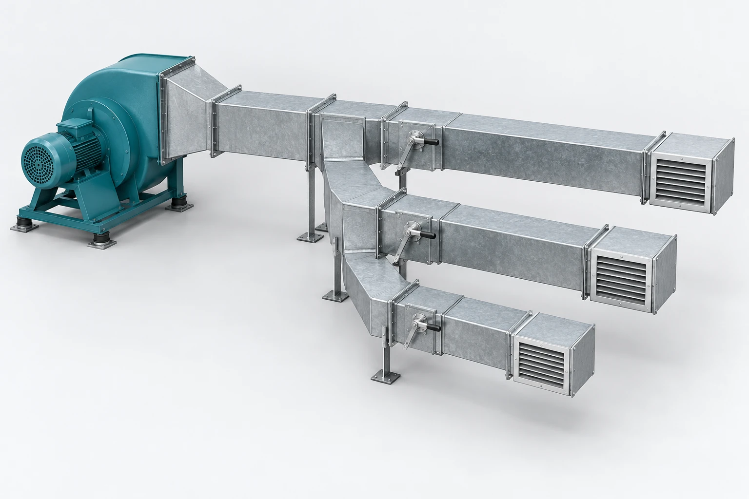
Common trunk → branches A, B and C
The schematic assigns route names and stated design-flow losses; physical branch length alone does not establish resistance.
02 · Exam-style model
This separate illustrative network needs at least 1.40 in. water across the shown paths at the stated design flows. Lower-loss routes require balancing; do not sum parallel branch losses.
Original teaching figure. The schematic and stated givens define the model; the 3D view illustrates the hardware. These are not actual examination exhibits.
| Condition or question | Governing decision | Error to avoid |
|---|---|---|
| A duct cross section is requested | Use , then convert dimensions to one consistent length basis. | Putting an inch dimension directly into a square-foot area calculation. |
| The fan must serve several parallel routes | Compare each complete route with its shared upstream/downstream losses included. | Adding every parallel branch drop in series. |
| Total and velocity pressure are supplied | Use on the same pressure datum. | Adding velocity pressure to total pressure to obtain static pressure. |
| An inlet elbow distorts the fan flow | Check installation system effect against the catalog inlet conditions. | Assuming a catalog curve remains valid after the inlet conditions change. |
On a narrow screen, scroll across the table to compare the decision and the error.
Relationships and their limits
Duct continuity
V in ft³/min, A in ft², v in ft/min.
Pressure relationship
Use matching pressure units and the specified measurement location.
| Symbol | Meaning | Units or basis |
|---|---|---|
| Volumetric airflow | cfm | |
| Duct cross-sectional area | ft² | |
| Mean air velocity | ft/min | |
| Total pressure | stated pressure units | |
| Static pressure | same pressure units | |
| Velocity pressure | same pressure units |
One decision, fully worked
Apply the method.
A duct carries 3,000 cfm. The design velocity limit is 1,000 ft/min. A rectangular section has a fixed internal width of 24 in. Find the minimum internal height ignoring available stock sizes.
- Divide airflow by allowable velocity to obtain required area.
- Convert the fixed width to 2 ft.
- Divide area by width, then convert height to inches.
The minimum idealized internal duct size is 24 in by 18 in.
Independent checkThe area is 432 in², or 3 ft²; 3,000/3 returns 1,000 ft/min.
Specialist extension
Translate ideal diffuser data into a usable check
A flow-area calculation establishes velocity through the specified area, not occupant-zone comfort or throw. Distinguish nominal face area, free area and the manufacturer’s effective area. Check the supplied throw, terminal velocity, layout and acoustic criteria independently rather than inferring them from a velocity alone.
A new applied case
A diffuser has 2.0 ft² face area and a supplied free-area fraction of 0.60. It handles 720 cfm. Find average velocity through free area.
Decision. The free-area velocity is 600 ft/min.
Cross-check. Using face area alone gives 360 ft/min and addresses a different area basis. Neither number alone proves acceptable throw.
Unit basis. Area is ft²; free-area fraction is dimensionless; volume is cfm; velocity is ft/min.
NCEES PE Mechanical Reference Handbook v2.1; see the module reference path.
Open targeted practice in the study studio →Transfer the method
Catch the common errors
- Treating square inches as square feet.
- Adding losses of separate parallel branches together.
- Substituting fan static pressure for total pressure without checking the definition.
Handbook navigation drill
Find it, then explain it.
Search: Duct Design
Locate duct friction and fitting information, then identify the input flow, geometry and pressure units.
Check your navigation
You can trace one complete route and distinguish its losses from those of other branches.
Reference path: §9.3.6–9.3.7, pp. 489–515. These are printed handbook page numbers; section names and search terms remain the primary navigation method. See technical review status.
Theory sources
- NCEES handbook v2.1, §§9.3.6–9.3.8.
- Grondzik and Kwok, Mechanical and Electrical Equipment for Buildings, 12th ed., §§12.9 and 12.11.
Worked examples and lesson prose are original ReasonSpan™ material. Obtain authorized publications separately; this preview does not reproduce the supplied books or handbook.