Decision Lab · E3 · Arrangement, capacity rate and NTU
Unknown outlet temperatures: choose the exchanger model
Choose a method before assuming an outlet temperature. Then test whether changing the flow arrangement preserves the result.
By the end of this workshop
- Choose a method that respects the supplied conditions.
- Explain how a changed condition affects the decision.
- Identify a physical or procedural cross-check and an applicability limit.
- Record the assumption you would verify next time.
Start with the complete model
Givens and assumptions
- Steady sensible exchanger, no external heat loss; constant properties.
- Hot inlet 160°F, hot capacity rate 2,400 Btu/(h·°F). Cold inlet 60°F, cold capacity rate 1,200 Btu/(h·°F).
- UA = 1,800 Btu/(h·°F); counterflow arrangement. Both outlet temperatures are unknown.
- Use the supplied relationships below. Capacity rates and UA keep the same units.
Supplied relationships
Use the appropriate arrangement with the stated capacity rates and inlet conditions.
01 · Equipment view
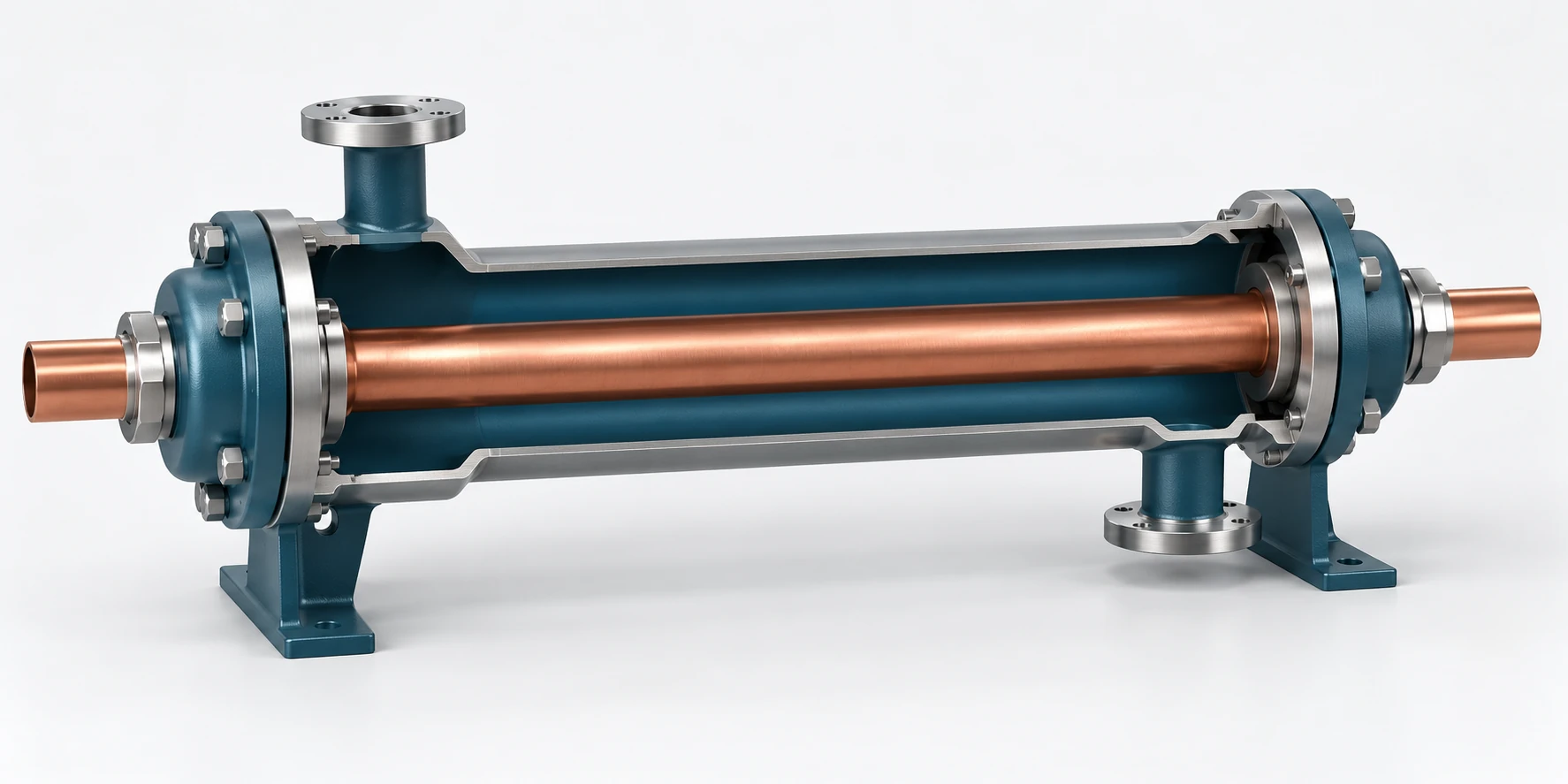
Hot stream · cold stream · two separated passages
The cutaway shows separate flow passages. The original schematic defines the inlet states and arrangement for each teaching model.
02 · Exam-style model
Both cases share the inlet temperatures, capacity rates and UA. Opposed arrows define counterflow; aligned arrows define parallel flow. Outlet temperatures remain unknown until the model is solved.
Original teaching figure. The schematic and stated givens define the model; the 3D view illustrates the hardware. These are not actual examination exhibits.
Study calculator, scratch notepad and whiteboard
Sketch a control volume or air path with a mouse, pen or touch. Ink stays in this page session and clears on reload. Use the response and reflection fields as a keyboard alternative. Sign in before starting and save a reflection to retain your reasoning.
1 · Choose the method
For the specified counterflow exchanger with both outlets unknown, which route determines duty without inventing terminal temperatures?
2 · Change the condition
Predict before you inspect the calculation.
Change the arrangement to parallel flow; preserve both inlet states, capacity rates and UA.
- Parallel flow; hot inlet 160°F, cold inlet 60°F, = 2,400 and = 1,200 Btu/(h·°F), UA = 1,800 Btu/(h·°F).
- Use the supplied parallel-flow expression; constant properties and no loss.
Check the first decision to open the changed-condition response.
Reference navigation drill
Search concept: effectiveness, number of transfer units
Locate the arrangement-specific relationship in your authorized reference. Identify which stream supplies C_min and how the equal-capacity limit is handled.
Where this model stops
Original idealized sensible models. Shell passes, crossflow mixing, fouling, phase change and variable properties require the appropriate additional model. The schematic supplies givens, not calculated outlets.
The PE Mechanical: HVAC and Refrigeration examination uses the NCEES PE Mechanical Reference Handbook. These source links provide study context; they are not additional exam-day references.
- ASHRAE · fundamentals of heat transfer ↗
- NCEES · current PE Mechanical: HVAC and Refrigeration specification ↗
Found an unclear condition or calculation? Include workshop exchanger-arrangement and the step in your comment.
Share private feedback →