Skip to page content

PE Mechanical: HVAC and Refrigeration

Read the evidence. Choose the method. Make the decision.

Connect psychrometric chart readings and equipment curves to the actual air path, energy boundary and system constraint.

Explore the original visual lessons and method cards below. Free candidate sign-in opens 28 saved exercises; paid enrollment remains closed. Twelve response-format drills per program cover numeric entry, select-two, matching and graphic regions.

Equipment → schematic → engineering decision

Work through the visual method.

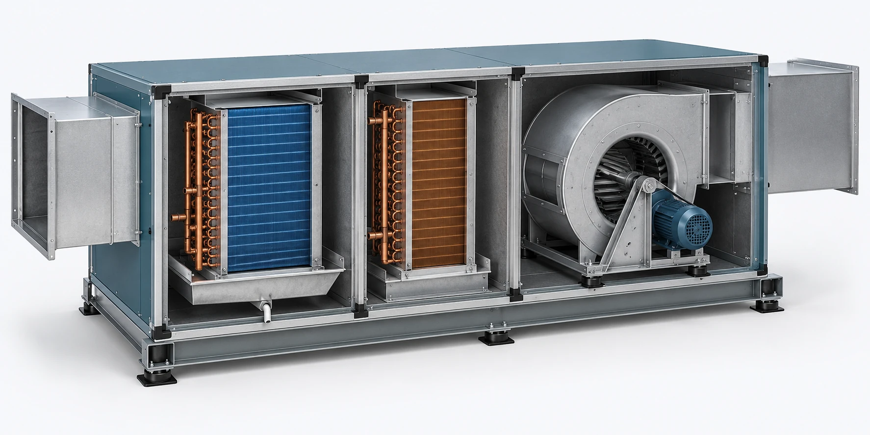
From the air handler to the psychrometric path

Conceptual three-dimensional cooling coil and reheat equipment.

From the air handler to the psychrometric path

100%Open in a new tab ↗

Scroll or swipe to inspect an enlarged exhibit. Use the supplied table for exact values.

From the air handler to the psychrometric path original schematic or chart.

Conceptual equipment companion and exact process schematic. Use supplied case values for calculations.

Trace the equipment

Follow mixing, wet cooling and downstream reheat. Identify which component can actually remove water.

Continue with the related program practice →

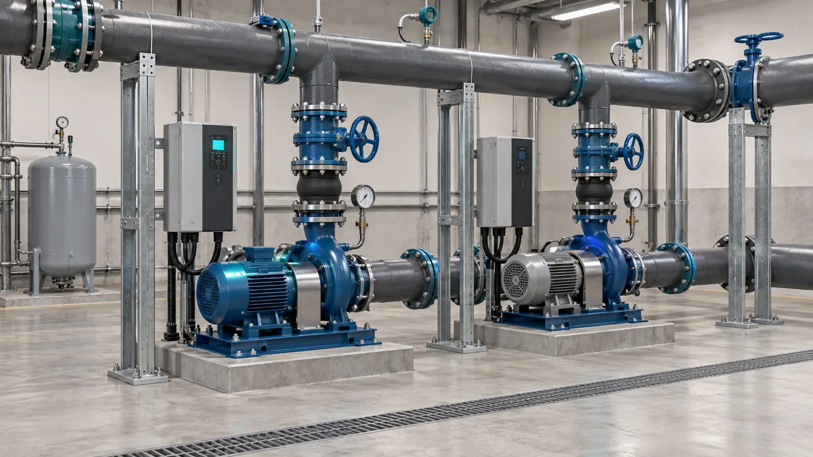
From two physical pumps to one installed operating point

Conceptual three-dimensional pair of pumps connected to common headers.

From two physical pumps to one installed operating point

100%Open in a new tab ↗

Scroll or swipe to inspect an enlarged exhibit. Use the supplied table for exact values.

From two physical pumps to one installed operating point original schematic or chart.

Existing equipment illustration paired with a new, precisely plotted USCS teaching curve. The linked narrated lesson uses its own stated SI example.

Identify the connection

Parallel pumps share inlet and discharge head; total flow is the sum of pump flows.

Continue with the narrated worked lesson →

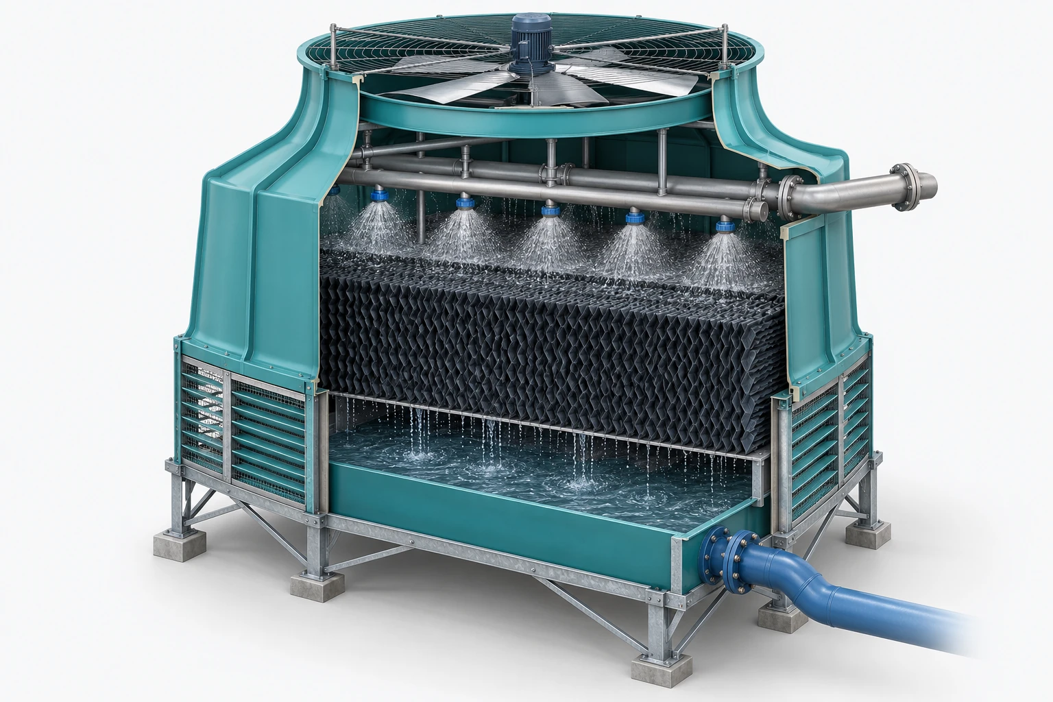
From the cooling tower to the wet-bulb limit

Conceptual three-dimensional cooling tower and water circuit.

From the cooling tower to the wet-bulb limit

100%Open in a new tab ↗

Scroll or swipe to inspect an enlarged exhibit. Use the supplied table for exact values.

From the cooling tower to the wet-bulb limit original schematic or chart.

Conceptual equipment companion and precise tower schematic. Use the individual exercise values, not values borrowed from another figure.

Draw the rejected-heat boundary

The tower receives evaporator load plus the compressor input that reaches the condenser, and any other explicitly included heat.

Continue with the related program practice →

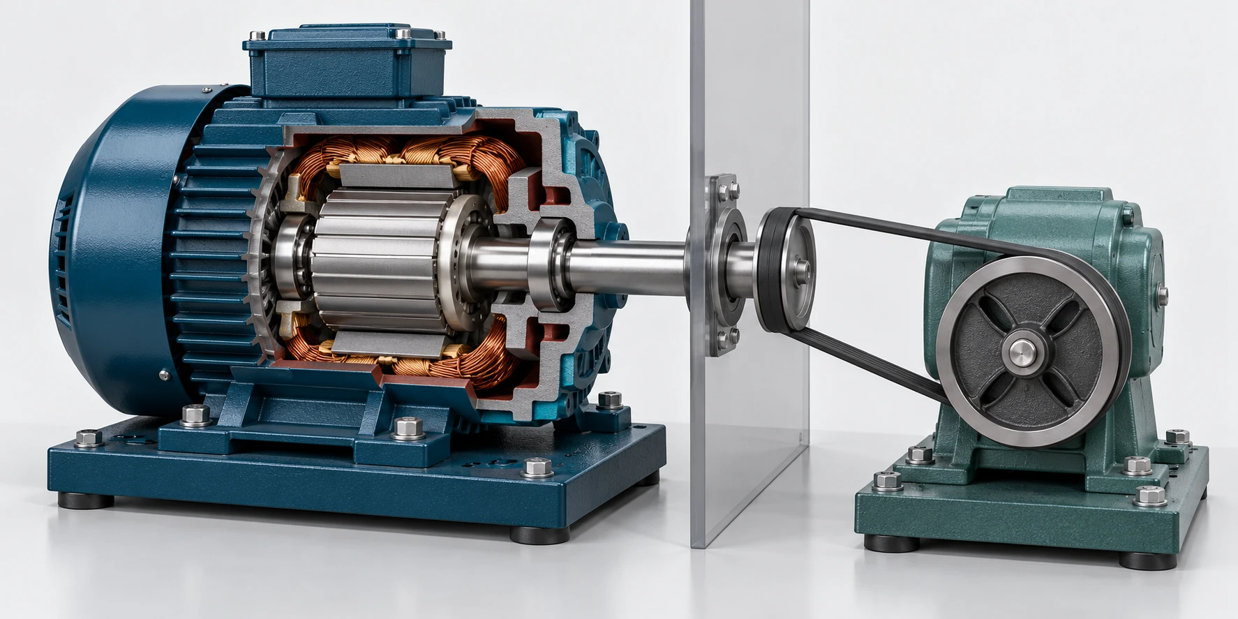
From the motor shaft to the room heat-gain boundary

Conceptual three-dimensional motor and shaft illustrating a room boundary.

From the motor shaft to the room heat-gain boundary

100%Open in a new tab ↗

Scroll or swipe to inspect an enlarged exhibit. Use the supplied table for exact values.

From the motor shaft to the room heat-gain boundary original schematic or chart.

Conceptual equipment companion with an exact energy-boundary schematic. The room boundary determines the load.

Locate motor and driven equipment

Identify which electrical losses and shaft-work dissipation occur inside the conditioned room.

Continue with the related program practice →

Practice reading a psychrometric chart

14.696 psia. This original orthogonal dry-bulb–humidity-ratio chart teaches the relationships; its geometry differs from the chart in your authorized reference. RH uses solid curves; other families use distinct line patterns.

Original psychrometric teaching chart

100%Open in a new tab ↗

Read axis units and line patterns first. Zoom and scroll to inspect labels. This original teaching graphic is separate from official examination software and references.

Original psychrometric teaching chart. Axes, units and curve families are labeled. Scroll horizontally or enlarge for legible readings.
How to read the chart and handle precision
  1. Locate two independent known properties at the stated pressure. Interpolate between adjacent curves.
  2. Read W horizontally; read dry bulb vertically. Trace the labeled enthalpy, volume or wet-bulb family as requested.
  3. Sensible heating and cooling at fixed W move horizontally on this chart. Dew point follows the same W back to saturation.
  4. For these authored exercises, aim for about ±1°F in temperature, ±0.0003 lb/lb in W, ±0.5 Btu/lb in h, ±3 percentage points in RH and ±0.15 ft³/lb in v. These are teaching targets, not NCEES grading rules. Errors in differences can be larger.

Wet-bulb curves are calculated as thermodynamic wet bulb. They are close to, but distinct from, constant-enthalpy lines.

Original authored teaching material. Use your authorized examination references to rehearse the actual chart geometry, search headings and listed standards for your exam.

Keep the method beside your answer.

Sign in free to work all 28 exercises and save first responses, confidence, reasoning and later reflections.

Sign in and open the lab

Four method cards for the next problem.

Cover the explanation and state the method in your own words. Revisit a card after a missed problem, then apply it to a fresh question.

Method 1

Name the boundary

What crosses the chosen boundary? What stays inside?

Draw the room, plant, branch or construction quantity boundary. Name where every energy, mass or load contribution acts.

Reveal a check on the reasoning

An indoor motor driving outdoor equipment contributes indoor losses, while exported shaft work dissipates elsewhere.

Method 2

Fix the quantity basis

Are these quantities comparable before you combine them?

Write units beside every input. Identify actual or standard airflow, dry-air or total mass, dry or moist soil and bank, loose or compacted volume.

Reveal a check on the reasoning

Actual cfm requires specific volume at the actual measurement state. Standard cfm uses its explicitly defined reference density.

Method 3

Find the governing constraint

Which requirement limits the proposed design?

Calculate independent capacity, safety or performance limits separately. Enforce all required lower and upper bounds.

Reveal a check on the reasoning

Minimum coil area is the larger independent airflow or thermal requirement. Parallel route losses are compared rather than summed.

Method 4

Read, estimate, then verify

What should the sign and approximate magnitude be?

Read chart labels and pressure first. Estimate before calculating. Preserve enough precision internally and report a justified result.

Reveal a check on the reasoning

A chart reading is an estimate. Do not distinguish answers more finely than the plotted scale supports; numeric training tolerances are exercise-specific.

Content quality and review

These original exercises have undergone internal technical and software checks. View the review scope, completed checks and remaining validation steps. Suggested working times are study guides.