PE Architectural · hydronic systems
Parallel pumps: why the system flow does not simply double
Intersect original pump and system curves, solve the one-pump and two-pump duty points, and distinguish total flow from flow through each pump.
Reviewed for the current ReasonSpan™ exam profile · Updated October 11, 2026By the ReasonSpan™ editorial team · Our content standards
Use total system flow and per-pump flow deliberately
Two identical pumps have the supplied curve Hp = 60 − 0.002q²; the system curve is Hs = 10 + 0.001Q². Heads are metres and flow rates are L/s, with coefficients defined for those units. Identical pumps at identical speed share total flow equally in parallel. Ignore control changes, efficiency and cavitation for this limited operating-point calculation.
01 · Equipment view
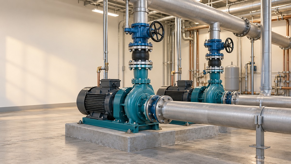
Pump 1 + pump 2 · common suction and discharge headers
Trace each pump branch between the same two headers, then add branch flows at their common head.
02 · Exam-style model
Curves are drawn from the supplied exercise equations. Circle A marks one-pump operation; square B marks two-pump operation. The plotted Q is total system flow.
Original teaching figure. The schematic and stated givens define the model; the 3D view illustrates the hardware. These are not actual examination exhibits.
Solve the one-pump intersection
With one pump, q = Q. Equating 60 − 0.002Q² to 10 + 0.001Q² gives Q² = 50/0.003. Q = 129.10 L/s and H = 26.67 m. Neither the static head alone nor the pump's shutoff head is the operating point.
Build the parallel curve at the same head
Each pump carries q = Q/2. The parallel head curve is therefore 60 − 0.002(Q/2)² = 60 − 0.0005Q². Its intersection with the system gives Q² = 50/0.0015, or total Q = 182.57 L/s and H = 43.33 m. Each pump now carries 91.29 L/s.
Total flow increases by 41.42%, not 100%. Adding a pump increases system friction loss and raises the shared head; each pump's flow falls relative to single-pump operation. Pumps in series add head at a common flow, a different arrangement.
| Operating state | Total Q (L/s) | Each operating pump q (L/s) | Shared head H (m) |
|---|---|---|---|
| A · One pump | 129.10 | 129.10 | 26.67 |
| B · Two identical pumps | 182.57 | 91.29 | 43.33 |
Before specifying actual equipment
Confirm manufacturer curves, speed, controls, efficiency, minimum flow, available suction head and the real system curve. These simplified curves demonstrate the governing method; they do not establish equipment suitability. Explain what would change if static head dominated the system rather than friction.
These are original instructional givens, separate from timed mocks. State assumptions before calculating and check the source edition required for your exam or project.
Sources and further reading
Exam requirements can change. Confirm current details with the organization that administers your exam and use the cited sources for the preparation principles summarized here.