ARE 5.0 Project Development and Documentation (PDD) · Complete public lesson
Offset-column transfer: trace the load before coordinating the detail
Identify the load-path discontinuity, check a simplified reaction model and request the information needed to coordinate the transfer zone.
Watch the narrated worked example
Trace an upper-column load through a 3D transfer overview and a coordination schematic, then choose the information needed before documents are issued.
The video teaches the load-path and coordination decision. The separate 240-kip calculation below is a supplied equilibrium screen, not the structural design of the illustrated assembly.
Read the video transcript
ReasonSpan™. A R E five point oh. Project Development and Documentation. Offset-column load transfer.
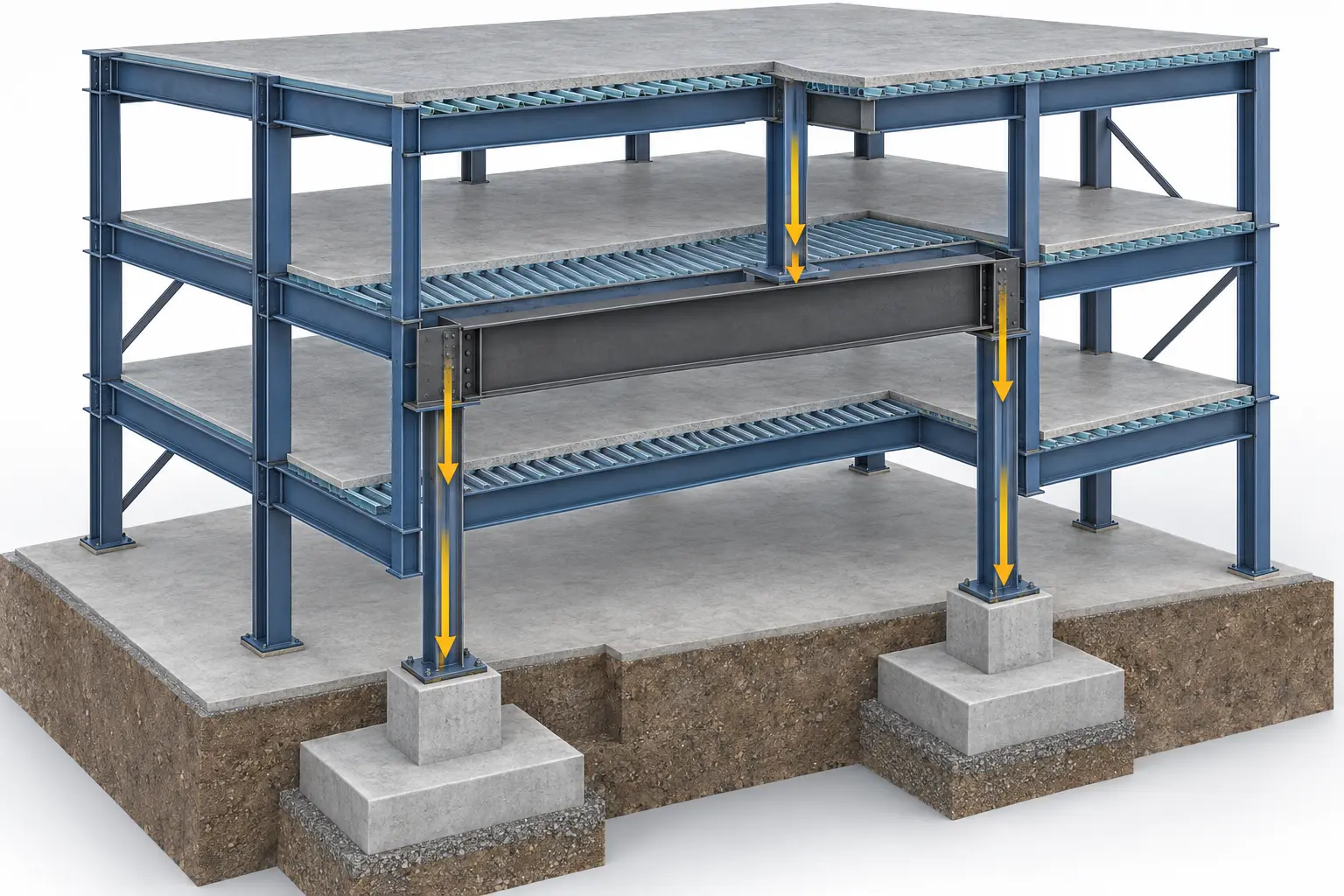
Locate the upper column, lower supports, transfer level, and foundations. The upper column reaction cannot simply disappear at the offset.
Trace load from slab to framing, upper column, designed transfer system, lower supports, and soil. Check each reaction and connection.
A preliminary tributary-area estimate is only a screen. The engineer must verify span, stiffness, support conditions, and load combinations. Reserve space for depth and adjacent systems.
Should the architect choose a beam depth, shift the foundation, or flag the discontinuity and request structural options and reactions?
Flag the discontinuity and reserve a coordination zone. The structural engineer designs the transfer, including downstream reactions. Drawing a deeper beam does not solve the analysis.
The same discipline applies when a duct crosses a beam: locate the exact conflict and coordinate a verified route before changing structure.
The situation and givens
An upper column lands between two lower supports instead of aligning with a lower column. The architect must coordinate the transfer level with structure, ceilings and building services. The following simplified model screens the reactions; it does not select a member.
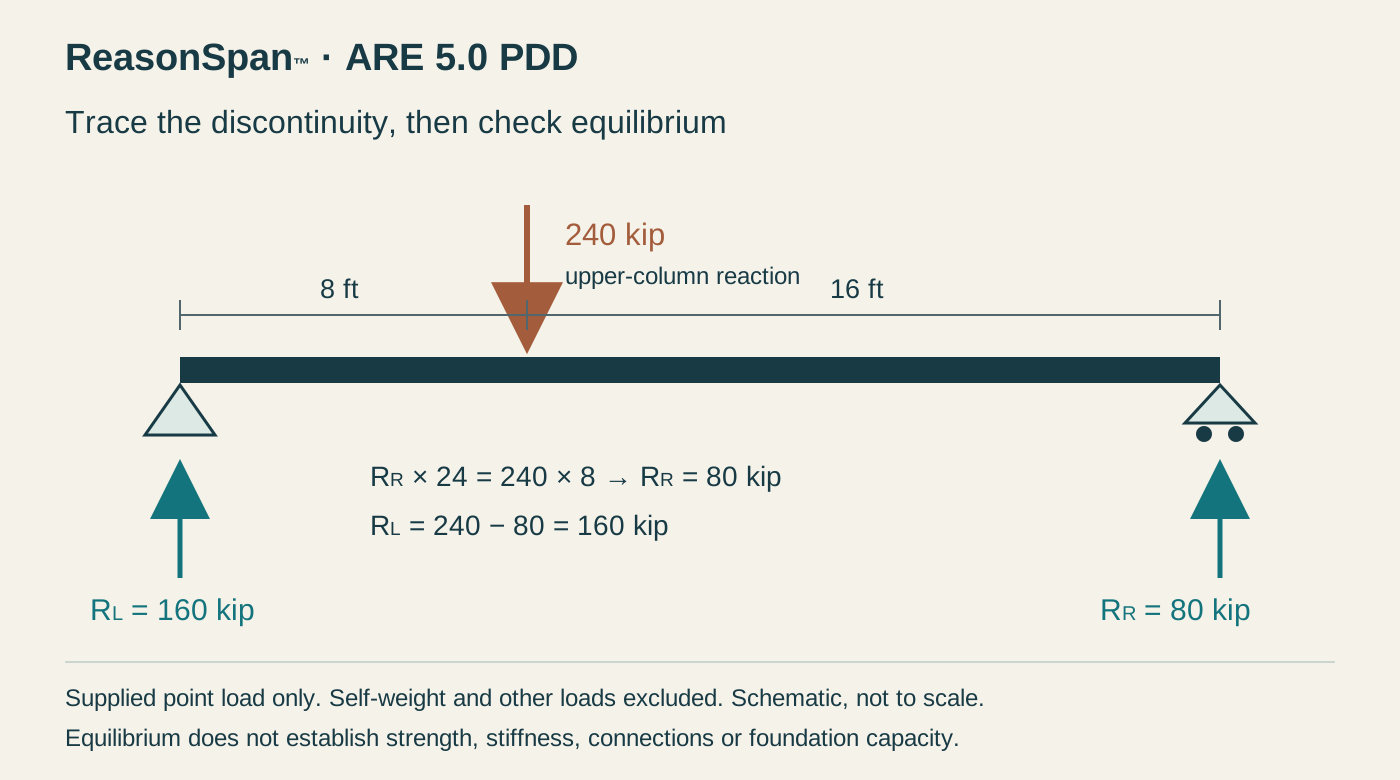
- A supplied upper-column reaction of 240 kips acts on a hypothetical simply supported transfer member.
- Support spacing is 24 ft; the upper-column reaction acts 8 ft from the left support.
- Ignore member self-weight and every other load solely for this equilibrium exercise.
- The structural engineer retains responsibility for the actual load combinations, stiffness, deflection, connections, supports and foundations.
- The proposed ceiling and service routes cross the transfer zone; no final beam depth has been confirmed.
Complete worked method
1. Locate the discontinuity
Trace the upper framing into the column and identify where the column no longer aligns with support below. The reaction still needs a continuous route through a designed transfer system, lower supports and foundations.
2. Check moment equilibrium for the supplied model
Take moments about the left support. The right reaction acts over the full 24 ft. The 240-kip load acts 8 ft from the left. The right reaction is 80 kips.
3. Check vertical equilibrium
The support reactions must sum to the supplied downward load. The left reaction is 160 kips. Equal reactions would require the load to act at midspan under these simplified conditions.
4. Turn the screen into a coordination request
Request the actual designed transfer system, member envelope, support reactions and connection zones from the structural engineer. Coordinate that information with service routes, ceiling elevations, fire protection and downstream supports. A deeper line on an architectural section is not a completed structural design.
5. Keep the model's limits explicit
Self-weight, other loads, stiffness, load combinations and actual support behavior were excluded from the screen. The calculated 160/80-kip split does not approve member capacity or foundation adequacy. Carry the assumptions into the coordination record.
Common errors and why they fail
- Splitting 240 kips equally ignores the off-center position of the supplied reaction.
- Selecting a beam depth from the reaction total alone omits span behavior, stiffness, connections and design loads.
- Treating the transfer as a local beam issue ignores the changed reactions reaching lower supports and foundations.
- Routing a duct through the transfer zone before its envelope is confirmed can create an unresolved structural conflict.
Apply the method
Which is the defensible coordination response to the supplied offset?
Change one condition
Move the same 240-kip load to 12 ft from the left support. Keep the idealized span and every other assumption unchanged. What happens to the reactions and the coordination responsibility?
Reveal the worked transfer
At midspan, R_R = 240 × 12 / 24 = 120 kips, and R_L = 120 kips. The reactions become equal in this simplified model. The structural engineer must still design the real transfer, connections and downstream system, and the architect must still coordinate the verified envelope with adjacent work.
Put the method to work
Try different questions to check whether you can identify the governing condition and explain the next action. The free sampler includes answers and worked explanations.