ARE 5.0 Project Development and Documentation (PDD) · Complete public lesson
Coordinate a gravity pipe within a ceiling zone
Combine slope, physical service depth and clearance into a coordinated section; select a change that preserves structural and ceiling requirements.
Watch the narrated theory example
Inspect premium 3D drainage cutaways with teaching callouts, then follow the slope, assembly depth and coordination decision. This visual decision clip also appears in the PDD theory program.
The video uses an 18 ft run at 1/4 in per ft, giving 4.5 in of fall. The worked exercise below uses a separate 40 ft run at 1/8 in per ft, giving 5 in of fall. Apply the same envelope method to each set of givens.
Read the video transcript
ReasonSpan™. A R E five point oh. Project Development and Documentation. Gravity drainage within a ceiling zone.
Reserve vertical depth for gravity drainage. Calculate fall, then test the entire physical route.
Establish the fixture connection, pipe invert, horizontal run, required slope, beam elevations, and proposed ceiling. Confirm all datums.
An eighteen-foot run at one quarter inch per foot needs four and one half inches of fall. That is an elevation change, not the total space required.
Add pipe diameter, fittings, hangers, insulation where present, tolerances, access, and structure. Compare the entire envelope with available ceiling depth.
Is calculated fall enough to approve the route? Can the contractor cut the beam? Or must the complete assembly and protected structure be checked?
Check the complete assembly. A correct fall does not prove a buildable path. Coordinate a new route, fixture or stack position, or ceiling geometry as needed.
Transfer the same space test to equipment rooms, where service and replacement clearance controls geometry beyond plan footprint.
The situation and givens
A coordination section shows a gravity pipe crossing a constant-depth ceiling zone under a beam. The project engineer has supplied the exercise slope. Determine whether the entire sloped run fits before issuing the reflected ceiling plan and plumbing coordination detail.
- Beam underside elevation: 132 in above finished floor
- Ceiling top elevation: 120 in above finished floor
- Horizontal run: 40 ft
- Specified exercise slope: 1/8 in per ft
- Pipe outside diameter: 4.5 in
- Insulation: 0.5 in radially, adding 1 in overall
- Support allowance: 1.5 in below the insulated pipe
- Required clearance above the highest pipe position: 2 in
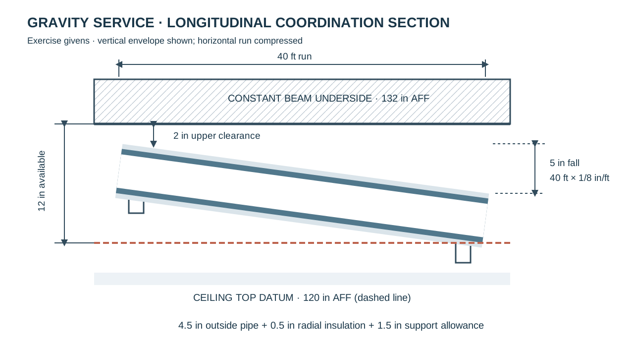
Complete worked method
1. Establish the available zone
Measure between the limiting surfaces using the same datum. Floor height alone cannot describe usable space above the ceiling.
2. Calculate the fall over the full run
The slope is given in inches per foot, so multiply by feet. Do not convert the 40 ft run to inches and then apply inches per foot as if the ratio were dimensionless.
3. Build the service envelope
Include both sides of the radial insulation, the supports, the specified upper clearance and the vertical fall. A pipe fitting upstream does not establish that the low end fits.
4. Resolve and document the shortfall
14 in required exceeds 12 in available by 2 in. Coordinate a shorter route, another approved zone or a properly reviewed ceiling/structure change. Cross-reference the approved route and elevations in the plumbing detail and reflected ceiling plan. Do not authorize a beam penetration or reduced required slope from this calculation alone.
Common errors and why they fail
- Checking only the 7 in insulated pipe-and-support assembly omits both the slope envelope and the required upper clearance.
- Adding only 0.5 in for radial insulation misses the opposite side of the pipe.
- An unreviewed beam penetration can change structural capacity and is not justified by a coordination conflict.
- Reducing the supplied slope or ceiling requirement requires the appropriate design decision, not a silent drawing edit.
Apply the method
What should the documentation team record for the current route?
Change one condition
An approved reroute reduces the run to 24 ft, with every other given unchanged. Does it fit?
Reveal the worked transfer
Fall becomes 24 × 1/8 = 3 in. The full envelope becomes 4.5 + 1 + 1.5 + 2 + 3 = 12 in, exactly the supplied zone. It meets the arithmetic limit with no extra tolerance. Verify constructability, routing, connections and actual installation tolerances before issue.
Put the method to work
Try different questions to check whether you can identify the governing condition and explain the next action. The free sampler includes answers and worked explanations.