Free ARE 5.0 Project Development and Documentation (PDD) wall-section practice
ARE 5.0 Project Development and Documentation (PDD) Wall-Section Practice Questions
Work six original PDD coordination questions on flashing, air barriers, movement joints, firestop systems, thermal bridges and opening dimensions.
Reviewed for the current ReasonSpan™ exam profile · Updated October 15, 2026By the ReasonSpan™ editorial team · Our content standards
Trace roof-to-wall continuity before accepting the opening change
Original coordination exercise: a roof edge meets a framed wall containing a revised opening. The wall water-control layer is drawn to drain over the head flashing, while a roof-to-wall transition is left as an unconnected dashed note. No detail shows how that transition connects to the wall or directs water away from the opening. The changed product dimension may be correct, but moisture continuity is unresolved.
Trace the roof and wall water-control layers through the intersection, identify every lap and termination, and obtain an explicit compatible transition detail before releasing the change. Air continuity needs its own trace; a drainage path does not establish an air seal. Roof overflow height, support, fire-resistance interfaces and opening clearances are separate checks. Do not fill a missing detail by assuming that every sealant or flashing product has the same movement and compatibility limits.
Trace the interface before choosing an answer
These six free original ReasonSpan™ questions practice selected assembly and documentation decisions. Every question is independent and supplies its own governing project facts. None appears in our protected diagnostic, mocks or paid question banks. The exercises are not NCARB questions or a complete PDD assessment.
Read each stated project requirement, identify the interface that must work, and choose the best coordination response. The diagrams are simplified learning exhibits, not construction details for use on a project.
1. Window-head drainage path
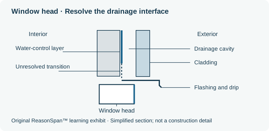
A drained exterior wall has a water-control layer behind a rainscreen cavity. Head flashing above a window projects beyond the cladding and ends in a drip. The detail does not show how the water-control layer connects to the flashing. The stated project goal is to drain cavity water to the exterior without directing it behind the window. Which revision best addresses the missing interface?
Show answer and worked explanation
Answer C: Detail a compatible water-control transition onto the head flashing.
Begin at the water-control layer and trace the drainage route downward. The existing flashing and drip address the final discharge, but the missing transition could allow water to pass behind the flashing.
Document the compatible lap or transition geometry and its support at an appropriate scale. Coordinate the window, membrane and flashing requirements instead of assuming one exposed sealant joint controls the concealed drainage path.
Why each option does or does not fit
- A. Seal the cavity outlet continuously across the window head.
- This would block the intended outlet. Surface sealing does not resolve the missing transition from the wall's water-control layer to flashing.
- B. Extend the interior finish farther over the window frame.
- Interior finish overlap does not establish a drainage connection on the wet side of the assembly.
- C. Detail a compatible water-control transition onto the head flashing. · Correct
- A supported, compatible transition must direct drainage-layer water onto the flashing and then out to the drip while preserving the cavity outlet.
- D. Add a larger exterior trim profile above the window.
- A larger trim profile can change appearance but does not demonstrate continuity between the concealed water-control layer and the flashing.
Remember the decision: A flashing projection is useful only when water can reach it from the controlling drainage layer.
2. Air barrier at a sleeve
A mechanical sleeve penetrates an exterior wall whose specified air-control layer is the exterior sheathing membrane. The sleeve has a decorative interior escutcheon, but no connection is shown between the sleeve and the membrane. The membrane manufacturer permits a compatible transition accessory at this interface. Which detail addition most directly restores the air-control path?
Show answer and worked explanation
Answer A: Show the approved continuous membrane-to-sleeve transition.
Identify the air-control layer named in the question rather than guessing that the interior finish is the air barrier. Follow that layer to the edge of the sleeve.
The project facts supply a permitted compatible accessory. Show the membrane-to-sleeve connection, then coordinate it with waterproofing, thermal and mechanical requirements that may also apply.
Why each option does or does not fit
- A. Show the approved continuous membrane-to-sleeve transition. · Correct
- Connect the specified air-control layer to the sleeve continuously using the compatible accessory and the required support and installation geometry.
- B. Increase the thickness of the decorative interior escutcheon.
- An interior trim change does not connect the specified exterior air-control layer to the penetration.
- C. Add insulation around the sleeve without a membrane connection.
- Insulation addresses heat transfer. Unless the specified assembly establishes otherwise, insulation alone does not seal an interrupted air-control layer.
- D. Reduce the sleeve diameter without updating the transition detail.
- A smaller sleeve changes the opening geometry but leaves the same undocumented discontinuity at the membrane.
Remember the decision: Resolve continuity at the layer responsible for the required performance.
3. Movement joint through an assembly
A structural movement joint separates two independently moving exterior wall segments. The structural drawings require the joint to accommodate the stated movement. The architectural detail shows rigid continuous finish backing bridging the gap, while the specified barrier system offers a movement-compatible transition. What is the best coordination response before the detail is issued?
Show answer and worked explanation
Answer D: Coordinate movable finishes, backing and barrier transitions at the joint.
The conflict is between independent structural movement and a rigid architectural bridge. Resolve that physical conflict across the whole assembly, not only at its visible face.
Check the required movement against the joint cover, backing, seals and barrier transition. Coordinate support on each side with the responsible disciplines before issuing the revised detail.
Why each option does or does not fit
- A. Keep the rigid bridge and add a visible joint line in the finish.
- A surface joint line does not remove the rigid connection that prevents the underlying segments from moving independently.
- B. Remove the structural joint callout from the architectural sheet.
- Omitting the callout conceals the conflict rather than satisfying the movement required by the structural design.
- C. Use a thicker continuous backing plate across the joint.
- A stronger rigid bridge still restrains the intended movement and may transfer unintended force between segments.
- D. Coordinate movable finishes, backing and barrier transitions at the joint. · Correct
- The affected layers must accommodate the required relative movement while maintaining their performance, including the compatible barrier transition.
Remember the decision: A movement joint must remain functional through each layer crossing it.
4. Firestop system and actual opening geometry
A project requires a tested firestop system for a pipe through a rated wall. The submitted system detail permits an annular space from 10 mm to 20 mm for the stated wall and pipe. The coordinated opening creates a 28-mm annular space. No approved alternative is documented. Which response addresses this conflict before installation?
Show answer and worked explanation
Answer B: Coordinate a documented system or opening revision that fits the conditions.
The problem provides the relevant limit, so no code-table recall is needed. Compare the 28-mm condition with the documented 20-mm maximum.
The response is a coordination task, not an instruction to improvise a field repair. Obtain an applicable system or review the proposed opening change with the responsible team, then update the detail and specification references.
Why each option does or does not fit
- A. Use the same product and retain the unlisted 28-mm gap.
- The submitted system permits only 10-20 mm for the supplied assembly. Product identity alone does not establish performance outside its documented configuration.
- B. Coordinate a documented system or opening revision that fits the conditions. · Correct
- Resolve the actual wall, pipe and opening configuration using an applicable documented system or a reviewed geometry change before installation.
- C. Accept the gap because the pipe material matches the submittal.
- Matching one component is insufficient when a stated dimensional limit of the same tested configuration is exceeded.
- D. Add decorative cover plates and leave the system detail unchanged.
- A cover plate hides the opening but does not supply evidence that the required firestop configuration accommodates the larger gap.
Remember the decision: A tested system must fit the complete configuration, including dimensions.
5. Shelf-angle thermal bridge
A steel shelf-angle support crosses the continuous exterior insulation and connects to the interior steel structure. The project requires a continuous thermal-control strategy at this support. A manufacturer offers an engineered thermally isolated support suitable for review against the project's load and enclosure criteria. Which next design action best addresses the identified thermal bridge?
Show answer and worked explanation
Answer C: Evaluate the isolated support and coordinate structure and control layers.
Identify the conductive path from the interior steel to the exterior support. The interruption is in the thermal-control strategy; a drainage or appearance change does not address that path.
The proposed system is a candidate for coordinated review, not automatic approval. Verify structural capacity and the adjacent enclosure interfaces as part of the same revised detail.
Why each option does or does not fit
- A. Increase cavity ventilation and keep the steel connection unchanged.
- Cavity ventilation does not interrupt conductive heat flow through the continuous steel support.
- B. Apply finish paint to the exposed face of the shelf angle.
- A finish coating does not provide the specified thermal isolation through the steel connection.
- C. Evaluate the isolated support and coordinate structure and control layers. · Correct
- Review the proposed thermal isolation together with load transfer, movement, water and air-control interfaces, and constructability before accepting the detail.
- D. Change the cladding color and retain the original support detail.
- Changing surface color does not remove the conductive bridge through the steel connection.
Remember the decision: Repair the governing performance path without losing the support's other functions.
6. Window substitution and opening coordination
A proposed replacement window has an overall unit width of 1,500 mm. The manufacturer's detail requires 20 mm of installation space on each jamb. The current architectural rough-opening dimension is 1,320 mm. Before issuing revised documents, which coordination target correctly addresses the dimensional change?
Show answer and worked explanation
Answer D: Check a 1,540-mm opening with the lintel, jamb and flashing details.
Use the overall unit dimension rather than a nominal designation. Add the required installation space at both jambs.
The calculated opening is a coordination target, not proof that the existing support can accommodate it. Review the lintel, anchorage, adjacent dimensions, head and sill flashing, air-control transitions and all affected document references before release.
Why each option does or does not fit
- A. Retain the 1,320-mm opening and update only the window schedule.
- The replacement unit is already wider than the existing opening. A schedule-only change leaves a physical conflict.
- B. Use a 1,500-mm opening and retain the existing jamb detail.
- This accounts for unit width but provides none of the required installation space.
- C. Use a 1,520-mm opening and verify the revised sill finish.
- This includes installation space on only one jamb. The stated allowance applies to both sides.
- D. Check a 1,540-mm opening with the lintel, jamb and flashing details. · Correct
- Add 20 mm on each side of the 1,500-mm unit, then coordinate the wider opening with structural support and the enclosure interfaces.
Remember the decision: A product change must propagate through dimensions, support, interfaces and document references.
Turn a missed detail into a focused review
If water and air continuity were difficult, trace the controlling layer through a different assembly. If movement or firestop limits were missed, separate the stated performance requirement from the physical configuration. If the opening calculation was correct but coordination was incomplete, list every affected drawing, schedule and specification.
The free interactive PDD sampler uses different items and exhibits. It provides another format preview; neither these learning exercises nor the sampler establishes readiness for the whole division.
Sources and further reading
Exam requirements can change. Confirm current details with the organization that administers your exam and use the cited sources for the preparation principles summarized here.