PE Architectural Engineering · Complete public lesson
Roof tributary width: line load, reactions and bending
Translate roof area load into beam line load, include beam self-weight once and connect equilibrium to shear and moment diagrams.
Roof load paths: tributary width to beam reactions and moment
Roof load paths. Before calculating beam reactions or bending moment, convert the roof's area load into the line load delivered to the beam. This original example follows one-way roof loading through tributary width, equilibrium and the moment diagram.
The narration and full worked method use the same original givens. Quiet gaps between sections let you inspect the diagrams and try the changed condition.
Read the video transcript
ReasonSpan™. P E Architectural Engineering. Roof tributary load paths.
Before calculating beam reactions or bending moment, convert the roof's area load into the line load delivered to the beam. This original example follows one-way roof loading through tributary width, equilibrium and the moment diagram.
The beam is simply supported over twenty feet and carries uniform loading along its full span. Adjacent roof spans extend ten feet to each side. Half of each adjacent span contributes to this beam, giving five plus five, or ten feet of tributary width. Supplied roof dead load is twenty pounds per square foot and roof live load is twenty pounds per square foot. Roof dead load excludes the separately supplied beam self-weight of ten pounds per foot. These are unfactored instructional loads.
Add the two roof area loads. Twenty plus twenty gives forty pounds per square foot. Multiply by the ten-foot tributary width to obtain four hundred pounds per foot. Then add ten pounds per foot for beam self-weight. The full line load is four hundred and ten pounds per foot, or zero point four one zero kips per foot. Adding ten pounds directly to forty pounds per square foot would mix different quantities.
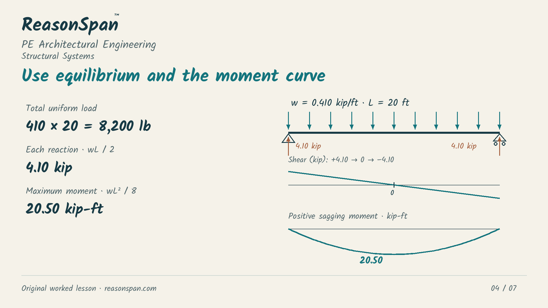
The total uniform load is four hundred and ten times twenty, or eight thousand two hundred pounds. By symmetry, each support reaction is four thousand one hundred pounds, or four point one zero kips. The shear diagram decreases linearly from positive four point one zero to negative four point one zero kips. Maximum sagging moment occurs at midspan. Line load times span squared divided by eight gives twenty thousand five hundred pound-feet, or twenty point five zero kip-feet. Moment is zero at the simple supports.
Change only the adjacent roof spans to twelve feet on each side. The tributary width becomes six plus six, or twelve feet. Keep beam length, roof area loads and beam self-weight unchanged. What are the new line load, reactions and maximum moment?
Forty pounds per square foot times twelve feet, plus the same ten-pound-per-foot beam self-weight, gives four hundred and ninety pounds per foot. Each support reaction becomes four point nine zero kips. Maximum moment becomes twenty-four point five zero kip-feet. Multiplying the old total line load by one point two would incorrectly increase the unchanged beam self-weight. Convert the changed roof contribution first, then add the fixed beam weight.
This calculation establishes demand under the stated load model. It does not prove a selected beam passes strength or serviceability checks. Confirm the actual load path, support behavior, applicable combinations and member properties before final design. Open the complete ReasonSpan lesson to inspect the exact tributary plan and beam diagrams, then test a different decision in the free Architectural sampler. The links are in the description.
The situation and givens
An instructional one-way roof model delivers uniform loading to a simply supported 20 ft beam. Adjacent roof spans extend 10 ft on each side. Use half of each adjacent span to establish this beam's tributary width, then calculate reactions and maximum sagging moment.
- Beam span L = 20 ft; pin and roller support model; full-span uniform loading.
- Adjacent roof spans = 10 ft on each side, giving 5 + 5 = 10 ft tributary width.
- Roof dead load = 20 psf, excluding beam self-weight; roof live load = 20 psf.
- Beam self-weight = 10 lb/ft. These are unfactored instructional loads, not a completed code design.
Complete worked method
1. Identify the tributary strip
One half of each adjacent one-way roof span contributes to this beam. Add 5 ft from each side, obtaining 10 ft. Using both full adjacent spans would double the roof contribution.
2. Convert area load to line load
Add roof dead and live area loads, multiply by tributary width, then add the separately supplied beam self-weight. psf × ft yields lb/ft.
3. Apply equilibrium
The total uniform load is 8,200 lb. Equal support reactions follow from the symmetric load and support model.
4. Read the shear and moment behavior
Shear decreases linearly from +4.10 to −4.10 kip, crossing zero at midspan. Sagging moment is zero at each simple support and reaches its maximum where shear is zero.
5. Separate demand from member acceptance
This analysis finds demand under the supplied unfactored load model. Actual member acceptance needs applicable load combinations, member properties, strength, deflection and other relevant design checks.
Common errors and why they fail
- Using 20 ft of tributary width includes both full adjacent roof spans instead of half of each.
- Adding 10 lb/ft directly to 40 psf mixes line and area quantities.
- Counting beam weight inside roof dead load and then adding it again double-counts a load excluded by the givens.
- Calling a calculated moment proof of beam adequacy omits member design and serviceability.
Apply the method
Which values follow from the stated baseline model?
Change one condition
Change only the adjacent roof spans to 12 ft on each side. Keep beam length, area loads and beam self-weight unchanged. Find w, reactions and maximum moment.
Reveal the worked transfer
Tributary width = 6 + 6 = 12 ft. w = 40 × 12 + 10 = 490 lb/ft. Each reaction = 490 × 20/2 = 4.90 kip. Maximum moment = 490 × 20²/8 = 24.50 kip-ft. Do not multiply the entire old 410 lb/ft by 1.2, because the beam self-weight is unchanged.
Put the method to work
Try different questions to check whether you can identify the governing condition and explain the next action. The free sampler includes answers and worked explanations.