PE Architectural Engineering · Complete public lesson
Power-factor correction: upstream current and real power
Convert real power to apparent power and upstream line current, calculate ideal shunt compensation, and preserve the distinction between supply current and load energy.
Power-factor correction: supply current versus real power
Can upstream supply current decrease while a building load still requires the same real power? Work this original three-phase example, keep kilowatts separate from kilovolt-amperes, and locate the current you are calculating.
The narration and full worked method use the same original givens. Quiet gaps between sections let you inspect the diagrams and try the changed condition.
Read the video transcript
ReasonSpan™. P E Architectural Engineering. Power-factor correction.
Can upstream supply current decrease while a building load still requires the same real power? Work this original three-phase example, keep kilowatts separate from kilovolt-amperes, and locate the current you are calculating.
The balanced load requires one hundred and twenty kilowatts from a four hundred and eighty volt, line-to-line supply. Its lagging power factor is zero point seven five. A shunt capacitor bank improves the power factor seen by the supply to zero point nine five. Keep real load power and supply voltage constant. Use an ideal sinusoidal steady-state model. The current measurement is upstream of the split between the load and the capacitor bank.
First calculate apparent power by dividing real power by power factor. Before correction, one hundred and twenty divided by zero point seven five gives one hundred and sixty kilovolt-amperes. After correction, the supply requires approximately one hundred and twenty-six point three two kilovolt-amperes. For balanced three-phase line current, divide apparent power in volt-amperes by the square root of three times line-to-line voltage. The upstream supply current falls from approximately one hundred and ninety-two point four five to one hundred and fifty-one point nine three amperes.
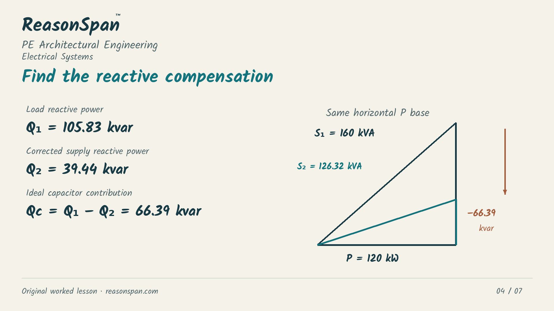
The two power triangles share the same one hundred and twenty kilowatt horizontal base. Reactive power is real power times the tangent of the power-factor angle. The load requires approximately one hundred and five point eight three kilovars. The corrected supply provides thirty-nine point four four kilovars. The ideal capacitor contribution is their difference, approximately sixty-six point three nine kilovars. The apparent-power side is the hypotenuse. Kilowatts and kilovars cannot be added arithmetically.
Keep the original load and voltage. Now target a lagging power factor of zero point nine zero instead of zero point nine five. What apparent power, upstream current and capacitor contribution would the same method predict?
At zero point nine zero, apparent supply power is one hundred and thirty-three point three three kilovolt-amperes. Upstream current is approximately one hundred and sixty point three eight amperes. The ideal capacitor contribution is approximately forty-seven point seven one kilovars. A less aggressive target needs less reactive compensation. In both cases the real load remains one hundred and twenty kilowatts. Do not present the supply-current reduction as an equal percentage reduction in the load's energy consumption.
The result applies to the supply upstream of the capacitor connection. It does not mean every motor winding or downstream conductor carries the corrected current. Actual selection also requires harmonic, switching, protection and equipment checks. Use the complete ReasonSpan lesson to inspect the one-line diagram and calculations, then try the separate free Architectural questions. The links are in the description.
The situation and givens
A balanced three-phase building load requires 120 kW from a 480 V line-to-line supply at a lagging power factor of 0.75. An ideal shunt capacitor bank raises the power factor seen by the supply to 0.95. Determine the apparent power, upstream line current and reactive compensation under the stated fixed-power model.
- Real load power P = 120 kW; line-to-line supply voltage VLL = 480 V.
- Original lagging power factor = 0.75; corrected lagging power factor = 0.95.
- Balanced sinusoidal steady state; constant real load power and voltage; ideal shunt compensation.
- Calculate current upstream of the split between the load and capacitor. The load branch is a different measurement location.
Complete worked method
1. Identify apparent power at each supply condition
Divide the fixed real load power by the supply power factor. kW and kVA describe different quantities.
2. Calculate upstream line current
Convert kVA to VA before applying the balanced three-phase relationship with line-to-line voltage. Keep the current measurement upstream of the capacitor connection.
3. Calculate reactive compensation
Reactive power equals real power times the tangent of the power-factor angle. The ideal capacitor supplies the difference between the original and corrected reactive demand.
4. Interpret what changed
Upstream current falls by approximately 21.05%. The real load remains 120 kW. The capacitor supplies reactive power locally; a 21.05% current reduction does not establish a 21.05% reduction in the load's energy consumption. Apparent power is the power triangle's hypotenuse, not P + Q.
Common errors and why they fail
- Using P/V as a balanced three-phase line-current calculation omits both power factor and √3.
- Using kVA without converting to VA introduces a factor-of-1,000 error.
- Calling 151.93 A the unchanged load-branch current ignores where compensation is connected.
- Equating the current reduction with an equal percentage of real-load energy savings confuses current with real energy.
Apply the method
Which conclusion follows from the stated ideal correction to 0.95?
Change one condition
Keep the original load and voltage but target lagging power factor 0.90. Calculate apparent supply power, upstream current and ideal capacitor contribution.
Reveal the worked transfer
S = 120/0.90 = 133.33 kVA; I = (120,000/0.90)/(√3 × 480) = 160.38 A. Corrected Q = 120 tan(arccos 0.90) = 58.12 kvar; Qc = 105.83 − 58.12 = 47.71 kvar. Calculate with unrounded values before reporting two decimal places. The real load remains 120 kW.
Put the method to work
Try different questions to check whether you can identify the governing condition and explain the next action. The free sampler includes answers and worked explanations.